CRT back projecting TV with improved structure

A technology of TV and rear projection, which is applied in the field of CRT rear projection TV with improved structure, can solve the problems such as not being able to meet the demand, and achieve the effect of easy to solve the cooling problem and be conducive to heat dissipation

Inactive Publication Date: 2005-01-12
SHENZHEN SKYWORTH RGB ELECTRONICS CO LTD
View PDF0 Cites 0 Cited by
  • Summary
  • Abstract
  • Description
  • Claims
  • Application Information

AI Technical Summary

Problems solved by technology

But the existing CRT rear-projection TV obviously cannot meet the demand

Method used


Image

  • CRT back projecting TV with improved structure
  • CRT back projecting TV with improved structure
  • CRT back projecting TV with improved structure

Examples


Embodiment Construction

[0014] The present invention will be described in further detail below through specific embodiments and in conjunction with the accompanying drawings.

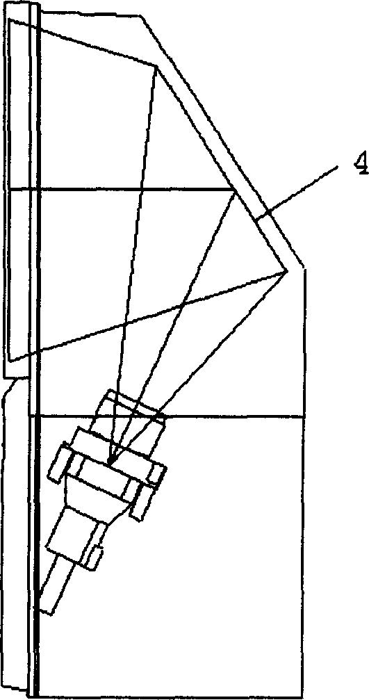
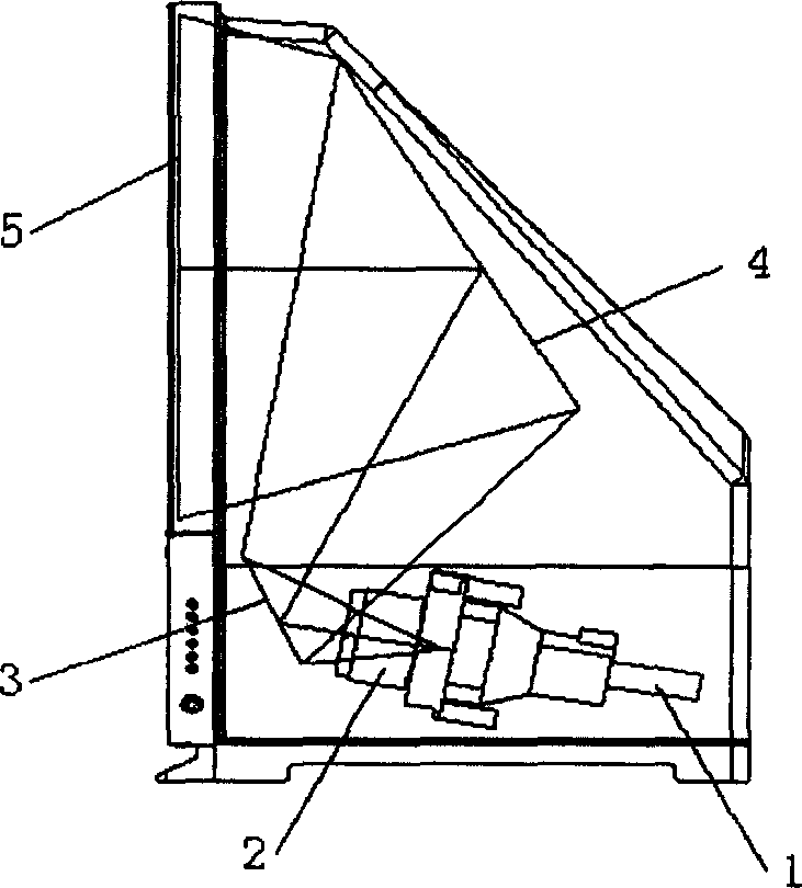
[0015] Such as figure 2 As shown, the CRT rear-projection television set of this a kind of improved structure comprises CRT1, projection mirror 2, primary reflection mirror 3, secondary reflection mirror 4 and screen 5, they are arranged in order according to the optical path, make described projection mirror 2 the CRT place The generated TV image is projected on the primary reflector 3, reflected by the primary reflector 3 to the secondary reflector 4, and finally reflected on the screen by the secondary reflector 4 for display.

[0016] The CRT1 and projection mirror 2 are located at the bottom of the TV, and the angle between the optical axis and the horizontal line is less than 45 degrees (when the TV is placed flat), usually less than 20 degrees, or even basically in the horizontal direction.

[0017] Of course, the opt...


PUM


Abstract

The invention consists of the CRT, the projecting mirror, the reflector and screen. There are two reflectors, they are primary reflection and secondary reflection; The above CRT, projecting mirror, primary reflection, second reflection and screen are set in turn by optical path to make projection of the TV image generated from CRT on primary reflection, the image is reflected to the second reflection from the primary reflection, finally they image is reflected to the screen to display from second reflection. Because of the image can reach the screen only through two steps reflection, the height of the base is greatly reduced.

Description

Technical field: [0001] The invention relates to a CRT (cathode ray tube) rear-projection TV set with an improved structure. Background technique: [0002] Rear-projection TVs are popular among consumers because of their large screens, clear and bright images, and such TVs have become one of the mainstream products in the color TV market at present. [0003] But existing CRT rear projection TV has a very big shortcoming, is exactly the height of base too high. Such as figure 1 As shown, since the CRT and the projection mirror are assembled into one, its length is very long and must be placed vertically, so its base cannot be very low. Therefore existing CRT rear projection color TV all is to be placed on the floor. [0004] Obviously, placing a CRT TV on the floor is not a very good option. First of all, there are many electronic components, CRTs, projection mirrors and other important components in the TV base, which are easy to get damp when placed on the ground; moreo...

Claims


Application Information

Patent Timeline
Patent Type & Authority Applications(China)
IPC IPC(8): H04N5/74
Inventor 王立勇何建民王和仁程自贵
Owner SHENZHEN SKYWORTH RGB ELECTRONICS CO LTD
Why Eureka
Try Eureka