Light guiding device and luminous sign object

A technology of light guide device and marker, applied in the directions of transportation, packaging, vehicle parts, etc., can solve problems such as poor pattern display effect, etc., and achieve the effect of uniform output light

Inactive Publication Date: 2005-01-26
HONG FU JIN PRECISION IND (SHENZHEN) CO LTD +1
View PDF0 Cites 4 Cited by
  • Summary
  • Abstract
  • Description
  • Claims
  • Application Information

AI Technical Summary

Problems solved by technology

[0004] In order to overcome the defect of poor pattern display effect of the prior art luminescent markers, the present invention provides a luminescent marker with better pattern display effect

Method used


Image

  • Light guiding device and luminous sign object
  • Light guiding device and luminous sign object
  • Light guiding device and luminous sign object

Examples


Embodiment Construction

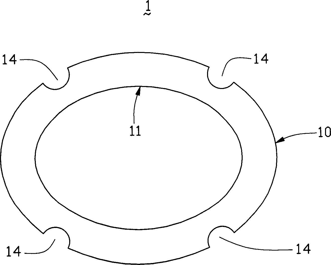
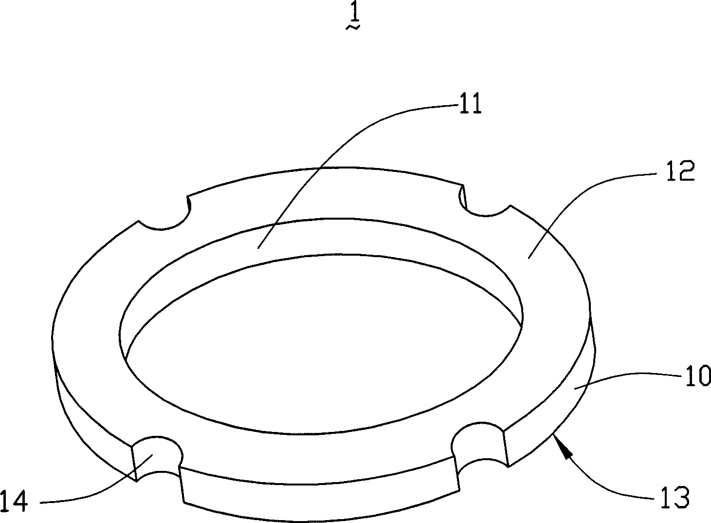
[0013] Please refer to figure 1 versus figure 2 , Are a schematic plan view and a three-dimensional schematic view of the first embodiment of the light guide device of the present invention. The light guide device 1 has an elliptical ring structure, which includes a top surface 12, a bottom surface 13 opposite to the top surface 12, an inner side surface 11, and an outer side surface 10 opposite to the inner side surface 11. The outer side surface 10 is provided with a plurality of grooves 14, the grooves 14 are light incident surfaces, and the inner side surface 11 is a light exit surface.

[0014] The light is incident from the groove 14 through the ring structure of the light guide device and then exits from the inner side surface 11 of the ring, so that the emitted light is more uniform. Wherein, the groove 14 and the inner side surface 11 can be subjected to surface treatment, such as sandblasting and atomization, so that the light can be scattered and uniformly injected in...


PUM


Abstract

The invention is a guide device, which is annular structure; it includes a top surface, a bottom surface relative to the top surface, an inner side surface and an external surface correspondent to the internal one. Parts of the external surface or the whole surface are the light incidence surface; the internal side surface is the emergent face.

Description

【Technical Field】 [0001] The invention relates to a light guide device and a light-emitting marker, in particular to a light guide device and a light-emitting marker applied to automobiles. 【Background technique】 [0002] A logo is usually set on a car. The logo usually includes a brand promotion pattern of the company that produces the car. The pattern not only has an aesthetic effect, but also plays a role in advertising. It works in bright places, but its publicity effect is limited in dark places. Therefore, the marker usually has a light source, such as a light emitting diode (LED), and the light emitted by the light emitting diode passes through a light emitting diode (LED). The plate-shaped light guide device made of transparent or translucent material is then irradiated onto the promotional pattern. However, the light emitted by the light-emitting diode is limited by the point light source itself, and its beam is concentrated within the maximum emission angle range. Moreo...

Claims


Application Information

Patent Timeline
Patent Type & Authority Applications(China)
IPC IPC(8): B60R13/00
Inventor 李俊佑蔡明江江宗韦
Owner HONG FU JIN PRECISION IND (SHENZHEN) CO LTD
Why Eureka
Try Eureka