Elastomeric guide-sleeve

A technology of guiding device and punch, applied in the direction of light impact tools, manufacturing tools, striking tools, etc., can solve problems such as poor integrity of components

Inactive Publication Date: 2005-02-02
ROBERT BOSCH GMBH
View PDF2 Cites 2 Cited by
  • Summary
  • Abstract
  • Description
  • Claims
  • Application Information

AI Technical Summary

Problems solved by technology

Poor integrity of components set up to meet these functions

Method used


Image

  • Elastomeric guide-sleeve
  • Elastomeric guide-sleeve
  • Elastomeric guide-sleeve

Examples


Embodiment Construction

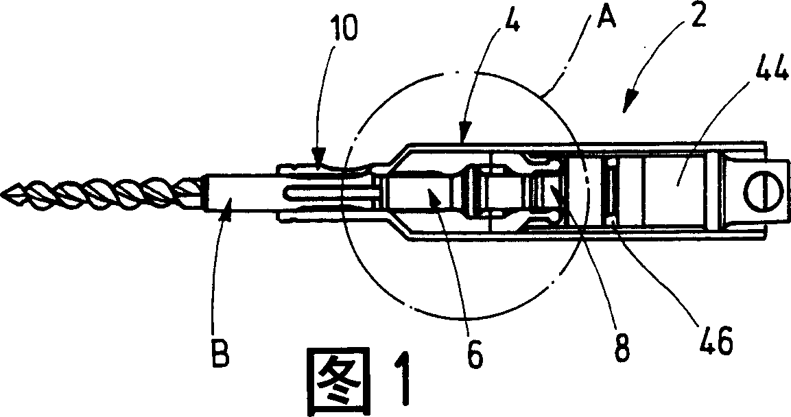
[0020] Shown in Figure 1 of the accompanying drawings, the punch assembly 2 of the impact mechanism of a portable electric impact drill or impact hammer machine (not shown) basically consists of a punch guide 4 and a Consists of an axially movable punch 6 which transmits the impact pulses of a hammer 8 of a percussion mechanism driven by the drive motor of a portable percussion drill or percussion hammer machine to a drill bit inserted in a tool holder 10 of the machine tool Or impact on tool B.

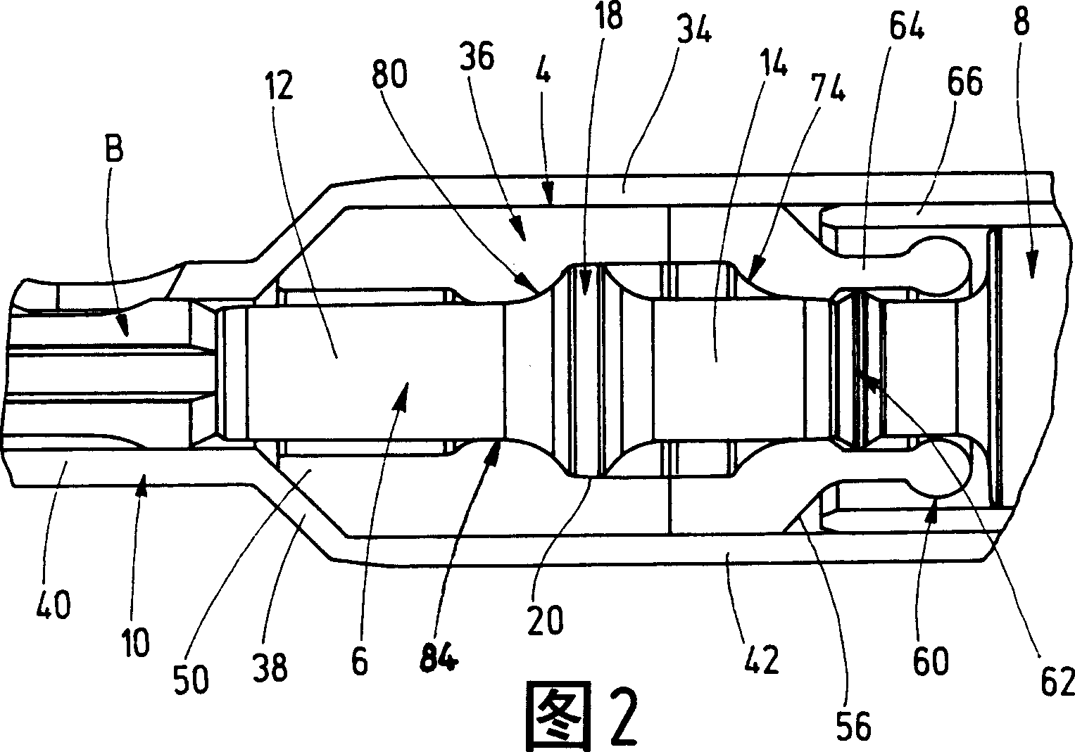
[0021] As shown most clearly in Fig. 4, the punch 6 made of solid steel consists of two elongated cylindrical end portions 12, 14 with chamfered flat end faces 16 and with these two end portions 12, 14 The thickened middle part 18 is connected and arranged between them. The central part 18 has a narrow, preferably but not necessarily cylindrical peripheral surface 20 in its center and is bounded on both sides by an oblique front side 22 and an oblique rear side 24 . The two side fa...


PUM


Abstract

The invention relates to a percussion drill and/or a jump bit, comprising a driving motor, a percussion mechanism and a toolholding device (10) for receiving cutters (B); wherein, the percussion mechanism comprises a punch (6) which can do axial movement in a punch guiding device (4) and act on the cutters; the punch guiding device (4) comprises an part (36) with an annular cross section which is made of elastomer material and surrounds the punch (6).

Description

technical field [0001] The invention relates to a percussion drill and / or percussion hammer machine with a drive motor, a striking mechanism and a tool holder for receiving a tool, wherein the striking mechanism comprises a tool movable axially in a punch guide and acting on Punches on knives. Background technique [0002] In order to seal the lubricated cavity against the surroundings on electrically driven portable electric percussion drills and / or percussion hammer machines, the percussion mechanism of the electric device for transmitting the percussion pulse usually includes a so-called punch, which Supported axially displaceably in the punch guide and impacted on the drive side by a hammer of the impact mechanism in the drilling and impact direction, the punch transmits the impact energy to the drive side of the tool received in the tool holder Ends. Hammer drills and / or percussion hammer machines of the type mentioned at the outset are known, for example, from DE 199...

Claims


Application Information

Patent Timeline
Patent Type & Authority Applications(China)
IPC IPC(8): B25D17/06
CPCB25D2250/365B25D2250/131B25D17/06B25D2250/191B25D2222/57
Inventor 阿希姆·迪塞尔贝格屈特·西贝尔
Owner ROBERT BOSCH GMBH
Why Eureka
Try Eureka