Internal flaw position detecting method in depth direction for glass base plate

A glass substrate, depth direction technology, applied in measuring devices, optical devices, instruments, etc., can solve the problem that the detection cannot clearly detect the glass substrate.

Active Publication Date: 2005-02-02
SAMSUNG CORNING PRECISION MATERIALS CO LTD
View PDF0 Cites 22 Cited by
  • Summary
  • Abstract
  • Description
  • Claims
  • Application Information

AI Technical Summary

Problems solved by technology

[0007] However, the mechanical image inspection method using a CCD camera has the disadvantage that it can only be applied to the i

Method used


Image

  • Internal flaw position detecting method in depth direction for glass base plate
  • Internal flaw position detecting method in depth direction for glass base plate
  • Internal flaw position detecting method in depth direction for glass base plate

Examples


Embodiment Construction

[0027] Hereinafter, preferred embodiments of the present invention will be described in detail based on the drawings.

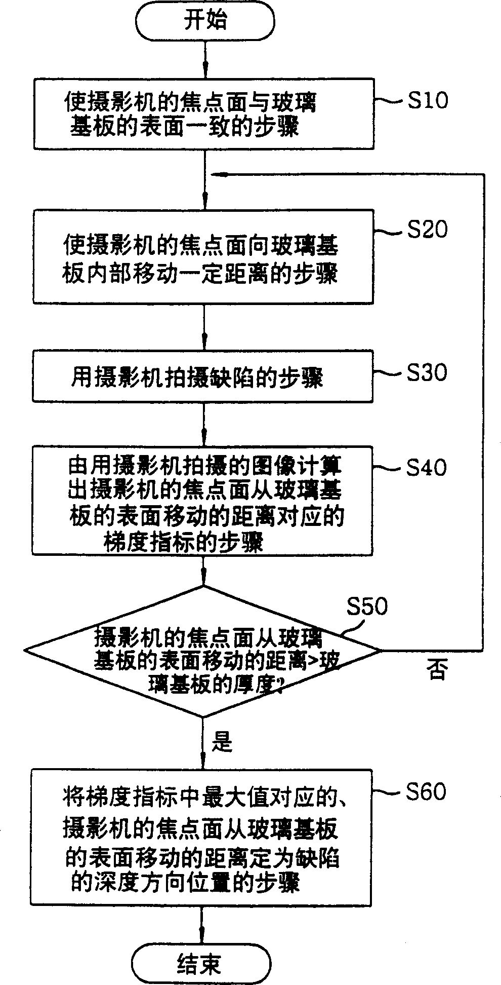
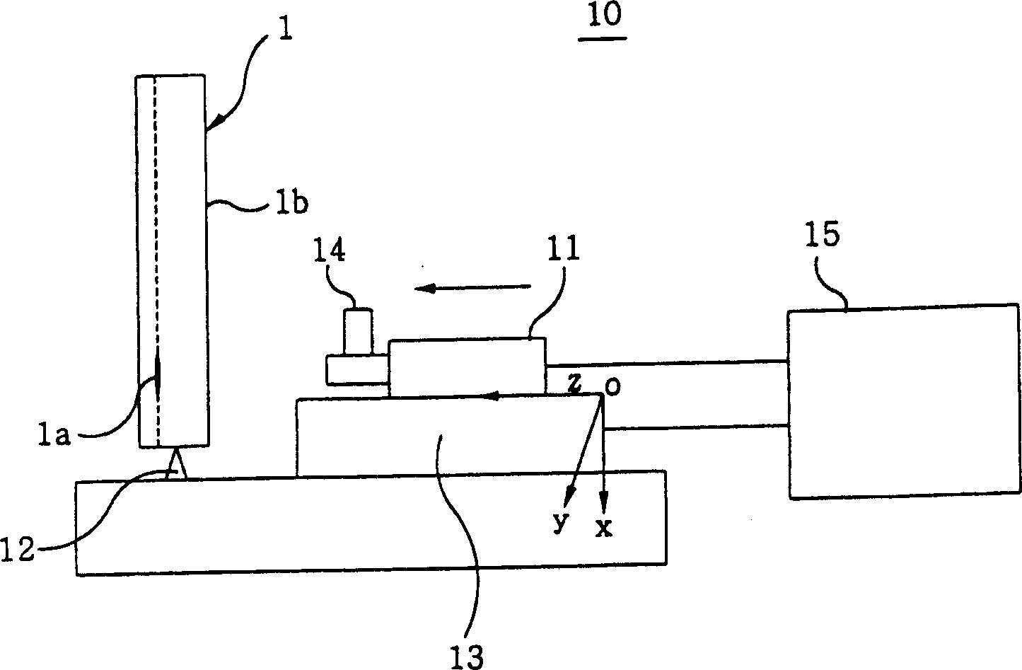
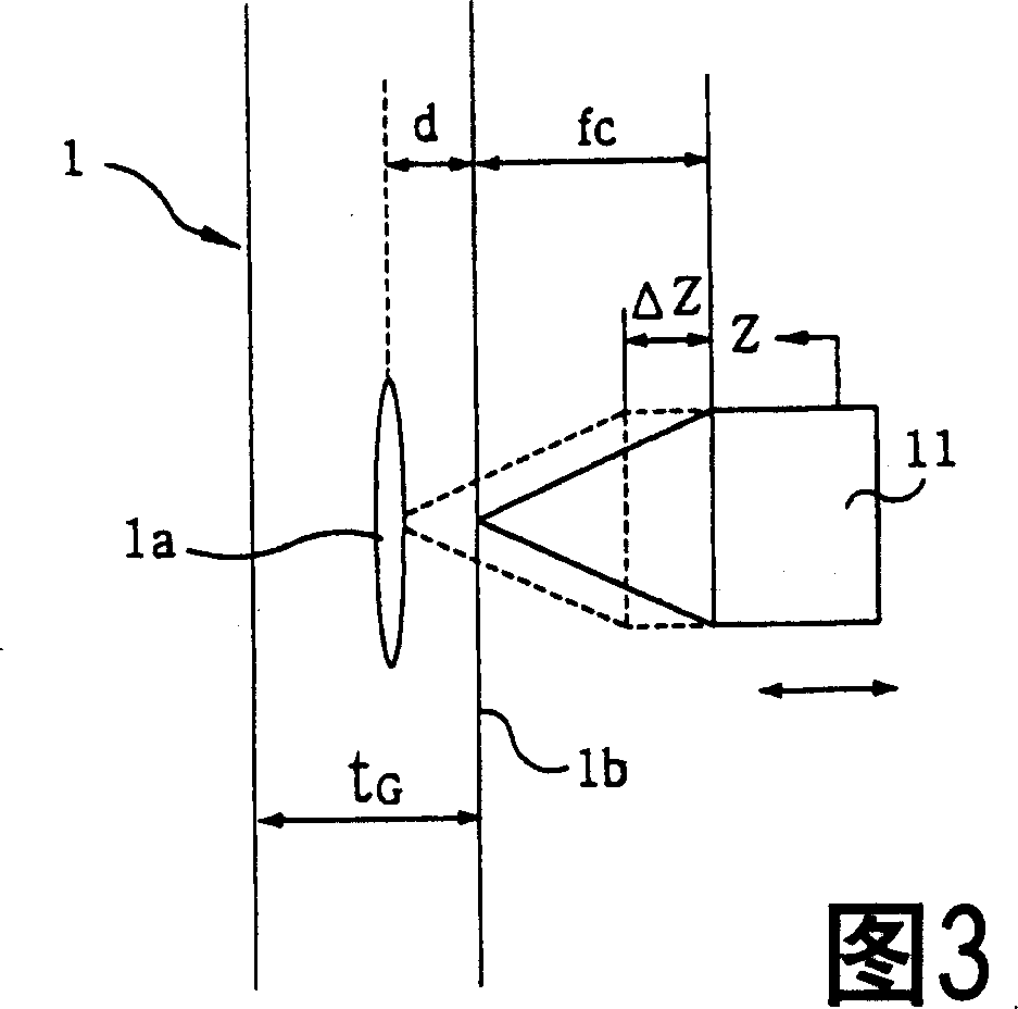
[0028] figure 1 It is a flowchart showing a method for detecting a position in a depth direction of a defect in a glass substrate according to the present invention, figure 2 3 is a schematic diagram showing an apparatus used in the method according to the present invention, and FIG. 3 is a schematic diagram showing an operation when the focal plane of the camera is aligned with the surface where the defect is located in the method according to the present invention.

[0029] The method for detecting the position in the depth direction of a defect in a glass substrate according to the present invention comprises the following steps: a step (S10) of making the focal plane of the camera 11 (such as a CCD camera) coincide with the surface 1b of the glass substrate 1 (that is, the surface 1b of the substrate 1 The distance between 1b and the camera 11 becomes t...


PUM


Abstract

To enable accurate and quick decision on the quality of a glass substrate, by precisely calculating the position of a defect in the depth direction, based on the image of a defect photographed, while moving the focal surface of a camera from the surface of the glass substrate to the inside, to obtain a clear image of a micro defects. The focal point of the camera is made to coincide with the position of a defect on the surface of the glass substrate; the gradient of illuminance in color in a boundary between the defect and the background thereof is calculated as a gradient index GI value with respect to a traveled distance from the glass surface, by using the image with the defect photographed, while the focal plane of a camera is moved from the surface of the glass substrate to the back side; the traveled distance, corresponding to the maximum of the gradient index GI value is determined as the position of the defect in the depth direction.

Description

technical field [0001] The present invention relates to a method for detecting the position in the depth direction of an internal defect existing in a glass substrate, more specifically, to a method for detecting the position in the depth direction of a defect in a glass substrate. The gradient indicator (Gradient Indicator) calculated by processing the image of the defect captured by the camera while moving the focal plane from the surface of the glass substrate to the inside of the glass substrate is related to the brightness of the illumination, the size, shape, boundary, The position in the depth direction of the defect is accurately calculated regardless of the thickness and the like, and a clear defect image can be obtained from this correct position even for fine defects. Background technique [0002] Generally, on glass substrates used in the manufacture of flat-panel displays such as TFT-LCD, PDP, and EL (Electro-Luminescence), if there are tiny defects such as tiny...

Claims


Application Information

Patent Timeline
IPC IPC(8): G01B11/00G01N21/896G01N21/958G02F1/13
CPCG01N21/896G02F1/1309
Inventor 李昌夏金昔俊丁址和
Owner SAMSUNG CORNING PRECISION MATERIALS CO LTD
Why Eureka
Try Eureka