Lens device and digital camera using same

A lens and frame technology, which can be used in installations, static cameras, components of color TVs, etc., and can solve the problem that the connection method cannot be directly used.

Inactive Publication Date: 2005-02-02
OM DIGITAL SOLUTIONS CORP
View PDF2 Cites 2 Cited by
  • Summary
  • Abstract
  • Description
  • Claims
  • Application Information

AI Technical Summary

Problems solved by technology

[0007] However, when an ultrasonic linear motor is used as the drive unit of the lens device, the conventional c

Method used


Image

  • Lens device and digital camera using same
  • Lens device and digital camera using same
  • Lens device and digital camera using same

Examples


Embodiment Construction

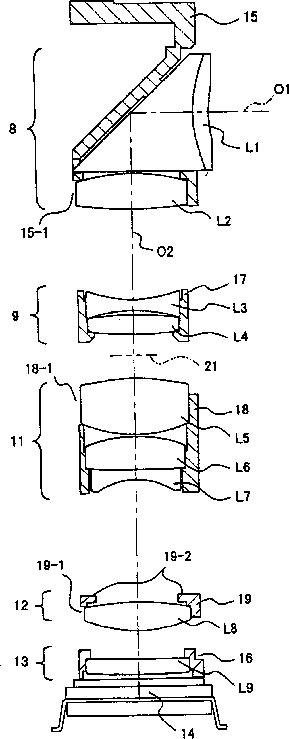
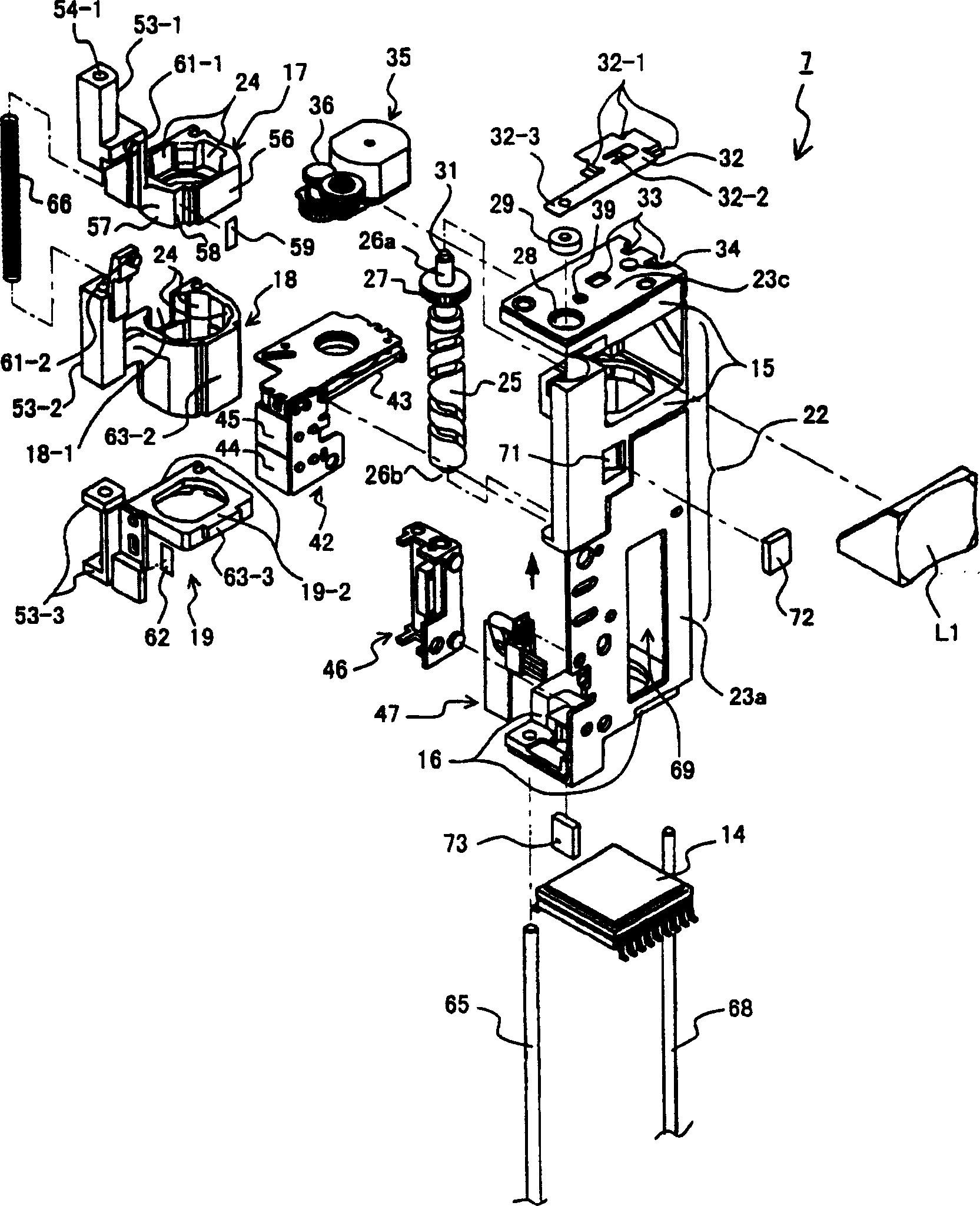
[0042] Hereinafter, embodiments of the present invention will be described with reference to the drawings. In addition, in the following description, the above-mentioned one main surface is composed of, for example, the surface of the metal frame 23a and the surface of the first fixed mirror frame part 15 integrally formed with the metal frame 23a, and the opposite main surface is composed of an open surface. In addition, the optical element is constituted by, for example, a prism L1, lenses L2 to L9, and the like, and the reflective optical element is constituted by a prism L1 and the like. In addition, the above-mentioned forming part is composed of, for example, the first fixed frame part 15 and the second fixed frame part 16, etc., the above-mentioned one side is composed of, for example, a metal frame 23b, and the other side facing it is composed of an open surface. Moreover, the said 1st guide member is comprised by the 1st guide shaft 65 etc., for example, and the said ...


PUM


Abstract

Provided is a lens device which is equipped with an ultrasonic linear motor and a coupling mechanism with a moving lens frame which is suitable for the linear motor, and a digital camera equipped with the lens device. The moving lens frame for focusing is constituted of a lens frame main body holding a moving lens, a bearing part and an engaging protrusive part, and the ultrasonic linear motor is arranged between the side surface of the main body and the protrusive part. A slot which is parallel with the moving direction along the optical axis of the main body is bored at the central part of the protrusive part, and a leaf spring engages in the slot from the opposite side. A pin member fixed and protrusively provided in the center of the motor is inserted through a gap formed between the energizing part of the spring and the left end of the slot, and its movement in the direction of an optical axis O2 in the slot is inhibited and its play in the vertical direction is allowed. Thus, the direction and the force of the movement of an oscillator in the direction of the optical axis O2 are accurately transmitted to the 3rd moving lens frame, and the vertical movement by the elliptical oscillation of the oscillator is absorbed and is not transmitted to the 3rd moving lens frame.

Description

technical field [0001] The present invention relates to a compact lens device and a digital camera using the same. Background technique [0002] Patent Document 1: JP-A-9-61692 (paragraph [0018], figure 1 ) [0003] Patent Document 2: JP-A-9-33782 ([Abstract], figure 1 ) [0004] Conventionally, in a lens device of a camera, in order to perform zooming and focusing according to an instruction from a control device, a frame unit holding a lens is freely movable in the direction of the optical axis. [0005] Since the mirror frame unit and the driving unit for driving the mirror frame unit are separate units, in order to transmit the driving force of the driving unit to the mirror frame unit, a connecting mechanism for transmitting the driving force between the two units is required. [0006] In this case, it is necessary to correct various positional deviations such as the mutual positional deviation of the two units, and the positional deviation of the parallel direction...

Claims


Application Information

Patent Timeline
IPC IPC(8): G02B7/08G02B7/04H04N5/225H04N101/00
Inventor 池町大白鸟和利佐藤有亮
Owner OM DIGITAL SOLUTIONS CORP
Why Eureka
Try Eureka