
Ultrasonic linear motor

a linear motor and ultrasonic technology, applied in piezoelectric/electrostrictive/magnetostrictive devices, piezoelectric/electrostriction/magnetostriction machines, electrical apparatus, etc., can solve the problems of inability to mold, inability to manufacture ceramic vibrators, and difficulty in subsequent cutting processes, etc., to achieve easy manufacturing and integration with other elements, simple structure, and easy manufacturing

Active Publication Date: 2010-10-19
IND TECH RES INST
View PDF14 Cites 3 Cited by
  • Summary
  • Abstract
  • Description
  • Claims
  • Application Information

AI Technical Summary

Benefits of technology

The present invention provides an ultrasonic linear motor with the following technical effects: a simple structure, easy manufacturing and integration with other elements, and full exploitation of vibrator oscillation. The motor includes a substrate, a vibrator with an oblique or curved face, and a slider with clamping portions for connecting with a power supply. The vibrator is made of a piezoelectric material and the power supply provides an oscillating voltage with the vibrator's resonant frequency. The motor allows for linear translation and can be used in various applications such as ultrasonic motors for linear motion.

Problems solved by technology

In addition, ultrasonic motors is self-locking when no power is applied, this saves energy when stationary, unlike the traditional electromagnetic type motors.
However, one problem currently encountered in designing ultrasonic linear motors is that the shapes of the ceramic vibrators cannot be easily manufactured, since ceramic is a fragile material.
If the shape of the vibrator is complicated, it cannot be molded in a single run, and subsequent cutting processes can be difficult (referring to U.S. Pat. Nos. 7,105,987, 7,053,525 and 7,205,703).
2008 / 073,999, all of which require additional bearing members, or referring to U.S. Pat. No. 6,747,394, which uses two vibrators and the performance of such motor may be affected since the dynamic characteristics of these two vibrators might be slightly different), and structures are more complicated.
Accordingly, assembly precision is critical for these types of motors, such that they cannot be manufactured at a low cost.
Furthermore, if the fixing structure of the vibrator is not well designed, it may suppress vibrator oscillation during operation.

Method used


Image

  • Ultrasonic linear motor
  • Ultrasonic linear motor
  • Ultrasonic linear motor

Examples


Embodiment Construction

[0027]The present invention is described by the following specific embodiments. Those with ordinary skills in the arts can readily understand the other advantages and functions of the present invention after reading the disclosure of this specification. The present invention can also be implemented with different embodiments. Various details described in this specification can be modified based on different viewpoints and applications without departing from the scope of the present invention.

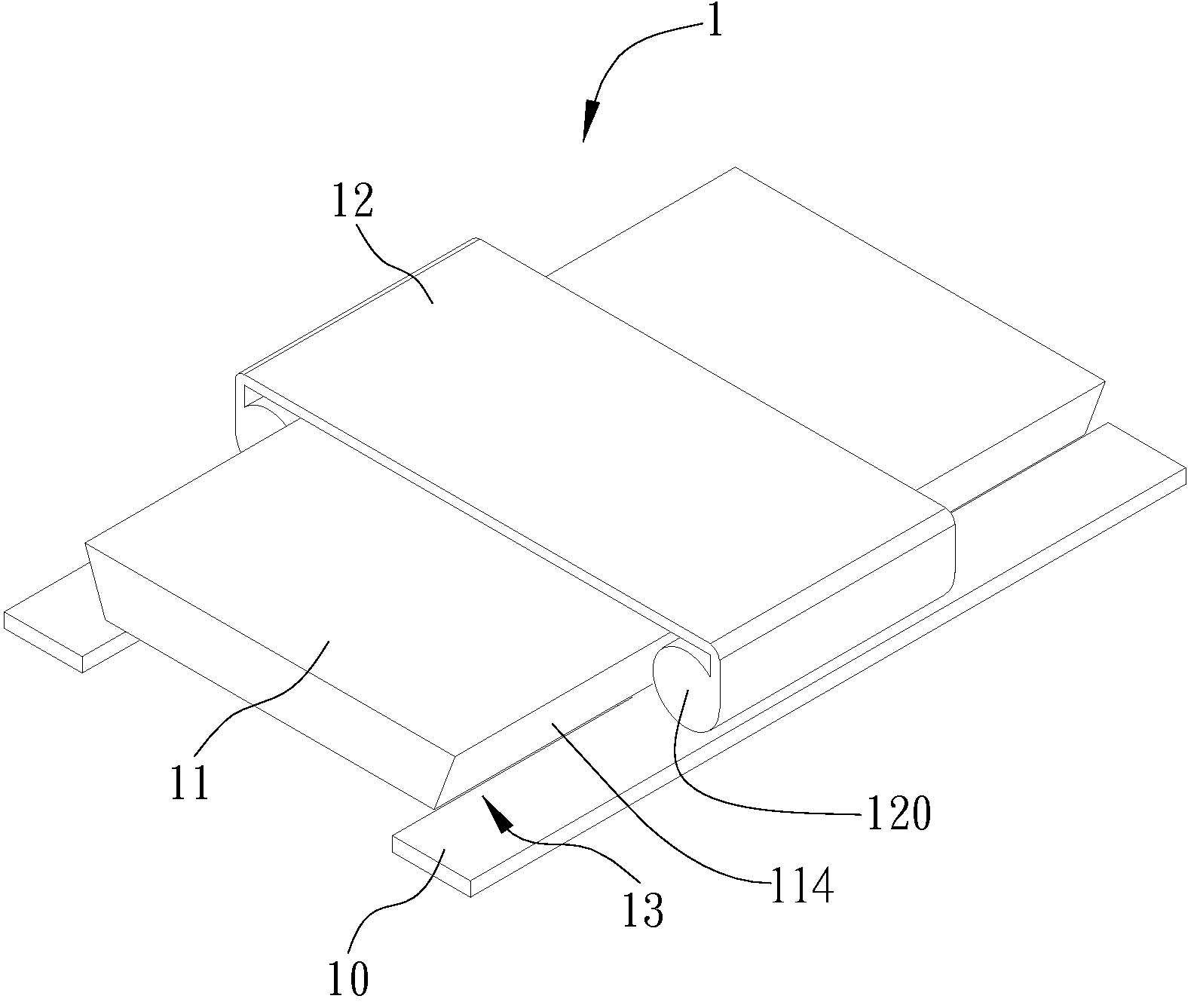
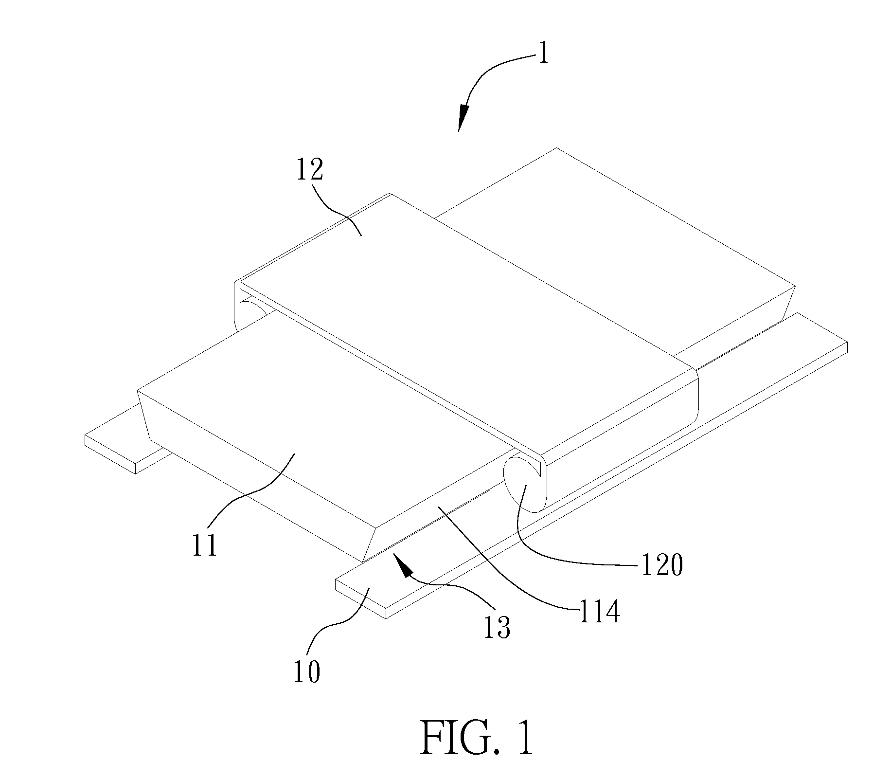
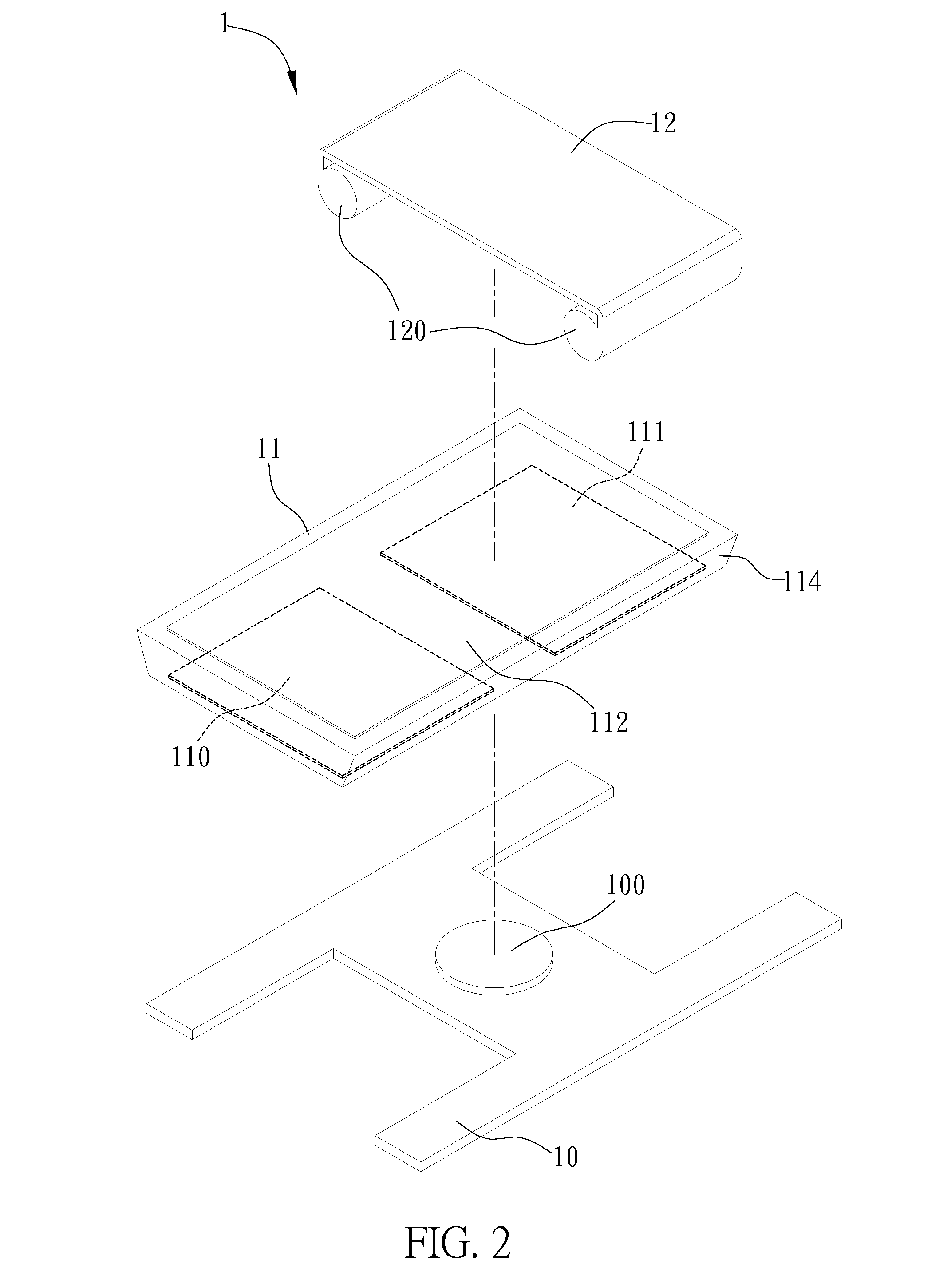
[0028]Referring to FIGS. 1, 2 and 3, a three-dimensional view, an exploded view and a cross-section view of an ultrasonic linear motor according to one embodiment of the present invention are shown, respectively. The ultrasonic linear motor 1 includes a substrate 10, a vibrator 11 and a slider 12, which are described in details as follow.

[0029]In this embodiment, the substrate 10 is an H-shaped slab or shell having a protrusion disposed on the center thereof. It should be noted that, in actual i...


PUM


Abstract

An ultrasonic linear motor includes a substrate; a vibrator disposed on the substrate having an oblique or curved face at two sides thereof forming concave receiving portions with the surfaces of the substrate; and a slider having clamping portions at two sides thereof for correspondingly clamping to the receiving portions, wherein the vibrator is for generating a driving force to the slider while connecting with a power supply, such that the clamping portions of the slider move within the receiving portions, thereby generating a linear translation. The present invention adopts a simple structure having few elements that enables easy manufacturing and integration with other elements, thus reducing manufacturing cost.

Description

FIELD OF THE INVENTION[0001]The present invention relates to an ultrasonic linear motor, and more particularly, to an ultrasonic linear motor that has a simple structure and only a few elements.BACKGROUND OF THE INVENTION[0002]Compared to traditional electromagnetic type motors, ultrasonic motors have various advantages, such as fast response, high precision, independence to electromagnetic interference, no complicated coil structure. Due to the linear driving characteristic of the ultrasonic linear motors, bulk and complicated screw conversion mechanism and power consumption during motion conversion can be eliminated. In addition, ultrasonic motors is self-locking when no power is applied, this saves energy when stationary, unlike the traditional electromagnetic type motors. Therefore, ultrasonic motors have gradually took over the place of electromagnetic motors and been widely used in producing micro-driving elements, such as in the driving element of a camera lens.[0003]The driv...

Claims


Application Information

Patent Timeline
Patent Type & Authority Patents(United States)
IPC IPC(8): H02N2/00
CPCH02N2/026H02N2/0055H02N2/002
Inventor CHEN, YI-CHENGWANG, YU-JENLI, CHIENYEH, CHIEN-SHIEN
Owner IND TECH RES INST
Learn More