Fiberoptic wavelength combiner

a wavelength combiner and fiberoptic technology, applied in the field of fiberoptic telecommunications, can solve the problems of significant weight, shock and vibration, and relative large devices, and achieve the effects of less weight, less shock and vibration, and small siz

Inactive Publication Date: 2005-04-21
LIGHTPATH TECH INC
View PDF6 Cites 4 Cited by
  • Summary
  • Abstract
  • Description
  • Claims
  • Application Information

AI Technical Summary

Benefits of technology

[0013] The fiberoptic wavelength combiner of the present invention is smaller in size than the prior art combination, weighs less, and is less susceptible to shock and vibration. Due to the fewer elements, the combiner of the present invention is also expected to cost less than the prior art combination.

Problems solved by technology

However, such a combination constitutes a relatively large device that has a significant weight and that is susceptible to shock and vibration.

Method used


Image

  • Fiberoptic wavelength combiner
  • Fiberoptic wavelength combiner

Examples


Embodiment Construction

[0017] Reference is now made in detail to a specific embodiment of the present invention, which illustrates the best mode presently contemplated by the inventors for practicing the invention. Alternative embodiments are also briefly described as applicable.

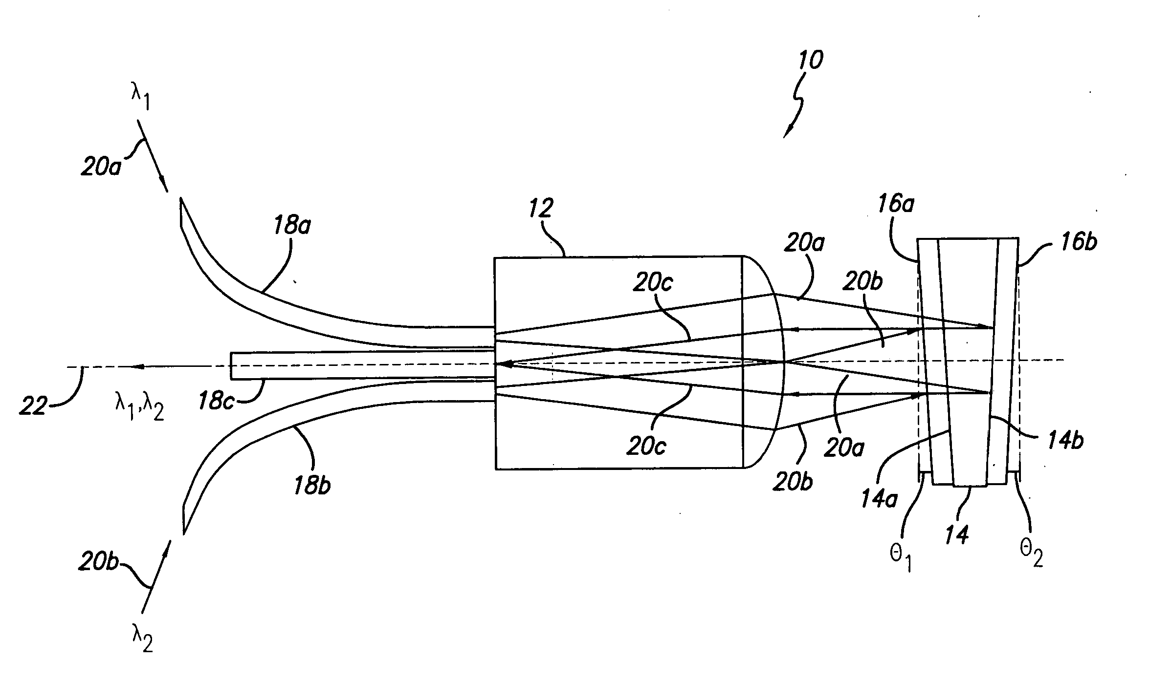
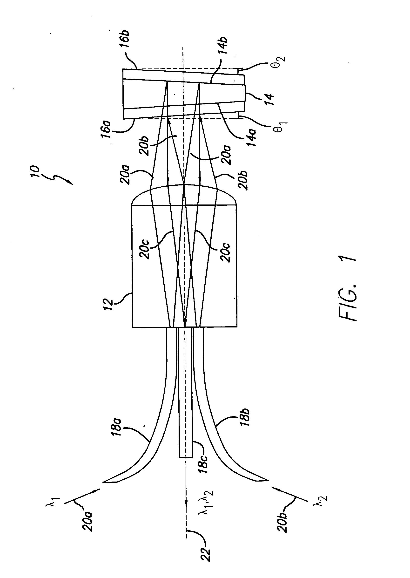
[0018] A fiberoptic wavelength combiner, utilizing a single collimator, serves the purpose of combining two different wavelengths into one fiber. One implementation of the device is shown in the sole FIGURE. Based on the disclosure herein, it will be readily apparent that other embodiments may also be envisioned.

[0019] The device 10 comprises a lens 12, a wedged mirror 14 having a first surface coating 16a on its front surface 1-4a and a second surface coating 16b on its rear surface 14b, and three fibers 18a, 18b, and 18c.

[0020] Light 20a, 20b of two different wavelengths, λ1 and λ2, respectively, enters the device 10 via optical fibers 18a and 18b. The fibers 18a, 18b are attached to the lens 12, such as by using known laser ...


PUM


Abstract

A fiberoptic wavelength combiner comprises: a collimating lens having a first surface and a second surface, opposite the first surface; two input optical fibers secured to the first surface, each input optical fiber conducting light at a wavelength that is different from other input optical fibers; a wedged mirror spaced from the second surface, the wedged mirror having a front surface facing the collimating lens and a rear surface, the front surface provided with a first reflective coating and the rear surface provided with a second reflective coating; and an output optical fiber secured to the first surface, whereby light from the input optical fibers is collimated by the lens and made incident on the wedged mirror and its first and second reflective coatings to thereby direct the light back through the collimating lens onto the output optical fiber. Further, a method of aligning the fiberoptic wavelength combiner is provided.

Description

TECHNICAL FIELD [0001] The present invention relates generally to fiberoptic telecommunications, and, more particularly, to combining two different wavelengths into one fiber. BACKGROUND ART [0002] A common task in fiberoptic telecommunications is to provide for input of two different wavelengths from two different sources into one fiber, e.g., a 1550-nm signal and a 980-nm pump. The combination of a dichroic mirror, three fibers, and three collimators is a popular and obvious solution. However, such a combination constitutes a relatively large device that has a significant weight and that is susceptible to shock and vibration. [0003] A need remains for a combiner that is simpler in construction, weighs less than the prior art combination, is less susceptible to shock and vibration than the prior art combination, and has a smaller cross-section. DISCLOSURE OF INVENTION [0004] In accordance with an embodiment of the present invention, a fiberoptic wavelength combiner is provided. The...

Claims


Application Information

Patent Timeline
Patent Type & Authority Applications(United States)
IPC IPC(8): G02B6/34
CPCG02B6/29362G02B6/2817
Inventor GUTIN, MIKHAIL A.HUNTER, BOYD V.YOST, DENNIS J.
Owner LIGHTPATH TECH INC
Why Eureka
Try Eureka