Earth leakage breaker

A leakage circuit breaker, main circuit technology, applied to circuits, electrical components, switches operated by ground fault current, etc., can solve the problems of not increasing the space for withstand voltage test switches, large development costs and time

Inactive Publication Date: 2005-02-02
FUJI ELECTRIC FA COMPONENTS & SYST CO LTD
View PDF2 Cites 13 Cited by
  • Summary
  • Abstract
  • Description
  • Claims
  • Application Information

AI Technical Summary

Problems solved by technology

[0013] However, the earth leakage circuit breaker of the above-mentioned single-body structure has the same external dimensions as the circuit breaker for wiring, and inside the main body case, such as Figure 9 As shown, functional parts for overcurrent protection and leakage protection are filled with almost no space left, and there is no room for adding a new switch for withstand voltage test.
Therefore, in order to secure a new space for the switch for the withstand voltage test to be built in the main body case, it is necessary to change the structural parts and their layout in design, especially the common parts and layout of the circuit breaker for wiring and the earth leakage circuit breaker. In the case of design changes, there is a problem that a large development cost and time are required

Method used


Image

  • Earth leakage breaker
  • Earth leakage breaker
  • Earth leakage breaker

Examples


Embodiment 1

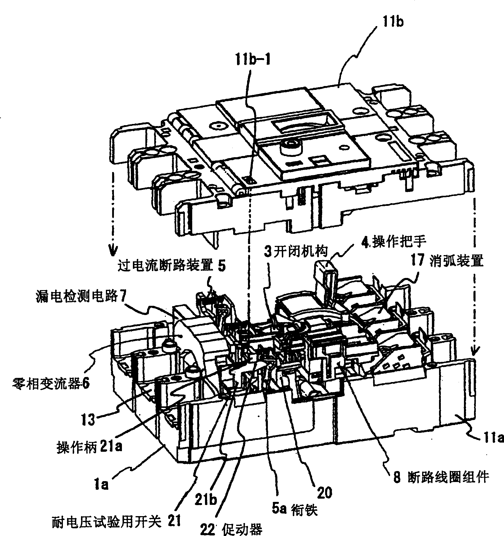
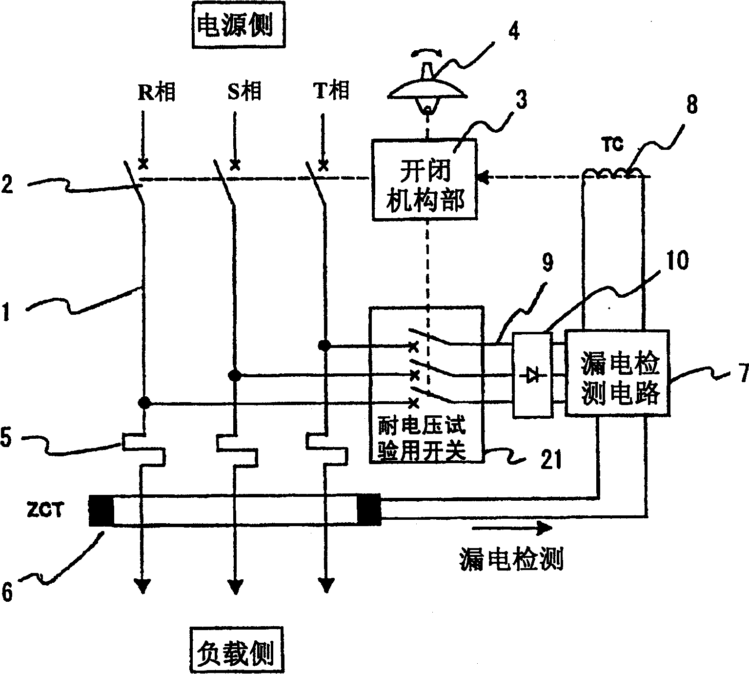
[0035] Figure 1 ~ Figure 4 It is a configuration diagram of an embodiment corresponding to aspects 1 to 3 of the present invention. The earth leakage circuit breaker of this embodiment and Figure 7 ~ Figure 9 The existing configuration shown is basically the same, and as shown in the circuit diagram of an earth leakage circuit breaker for a three-phase power supply in FIG. superior. Moreover, in the circuit diagram of FIG. 2, three power lines 9 corresponding to each of the R, S, and T phases are wired between the main circuit 1 and the leakage detection circuit 7, and the three-phase AC power is converted into DC by a rectifier circuit 10. , to supply power for the leakage detection circuit 7, and match with three power lines 9, the switch 21 for withstand voltage test has three contacts, but in such as Figure 7 In the case where the phase-to-phase voltage of the R-T phase of the main circuit 1 is supplied to the leakage detection circuit 7 as shown, the switch 21 for th...

Embodiment 2

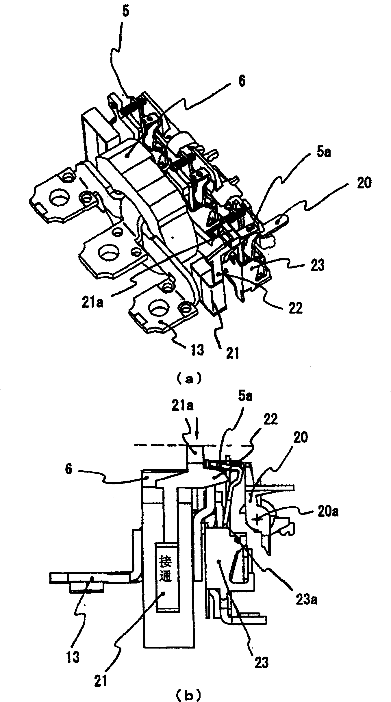
[0044] Next, use Figure 5 , Figure 6 The configuration and operation of an embodiment corresponding to the fourth aspect of the present invention will be described.

[0045] In the structure of the above-mentioned embodiment 1, the actuator 22 provided on the operating rod of the switch 21 for withstand voltage test is interlocked with the armature 5a as the operating end of the overcurrent breaking device 5, so that the armature 5a will open the circuit breaker horizontally. Lever 20 is driven to the snib release position. On the other hand, in this embodiment, the actuator 22 provided on the switch 21 for the withstand voltage test is connected to the disconnecting coil assembly 8 as an earth leakage circuit breaker (refer to Figure 7 , Figure 9 ) is interlocked with the sliding body 8a at the operating end, and the breaking cross bar 20 is driven to the latch release position through the protrusion 8a-1 provided on the sliding body (slider) 8a.

[0046] That is, on t...


PUM


Abstract

An earth leakage breaker includes a main contact, a switch mechanism, an operating handle, a leakage tripping device and an over-current tripping device having an earth-leakage-detection circuit disposed in a main-body case. A power-supply line connects the earth-leakage-detection circuit to the main circuit for supplying voltage between phases of the main circuit as a power source of the earth-leakage-detection circuit. Further, a test switch is provided for turning on and off a power-supply circuit of the power-supply line connected to the earth-leakage-detection circuit, and an operation of the test switch is linked to an ON / OFF operation of the switch mechanism.

Description

technical field [0001] The present invention relates to a leakage circuit breaker with overcurrent protection and grounding protection functions suitable for low-voltage power distribution systems, and more specifically, to a method for cutting off the leakage detection circuit from the main circuit when carrying out the withstand voltage test of the leakage circuit breaker protective device. Background technique [0002] As protectors for low-voltage power distribution systems, there are known circuit breakers for wiring and earth leakage circuit breakers. The earth leakage circuit breakers popular in China are generally earth leakage circuit breakers with overcurrent protection function and grounding protection function. In addition, for recent earth leakage circuit breakers, in order to improve the usability of the target party, earth leakage circuit breakers with the following structure have become mainstream: In the wiring circuit breaker of the same structure, the eart...

Claims


Application Information

Patent Timeline
Patent Type & Authority Applications(China)
IPC IPC(8): H01H83/02H01H71/12H01H83/04H01H83/14H01H83/20H01H83/22
CPCH01H83/04H01H83/226H01H83/20H01H83/144H01H2300/052H01H71/128A63F7/02A63F7/0058A63F2250/142
Inventor 浅野久伸浅川浩司高桥康弘
Owner FUJI ELECTRIC FA COMPONENTS & SYST CO LTD
Why Eureka
Try Eureka