Electric valve

A technology of electric valve and valve shaft, applied in the direction of lift valve, valve device, valve details, etc., can solve problems such as unsolved problems, and achieve the effects of preventing incoordination, improving lubricity, and reducing sliding resistance

Inactive Publication Date: 2005-02-09
FUJIKOKI MFG CO LTD
View PDF2 Cites 5 Cited by
  • Summary
  • Abstract
  • Description
  • Claims
  • Application Information

AI Technical Summary

Problems solved by technology

[0013] However, the nickel-plated metal layer described in Patent Document 2 is provided on the interengaging threaded portion of the valve shaft holder and the guide bushing, and does not solve the problem of fatigue resistance of the thrust nut 33 or the flat metal sheet 60.

Method used


Image

  • Electric valve
  • Electric valve
  • Electric valve

Examples


Embodiment Construction

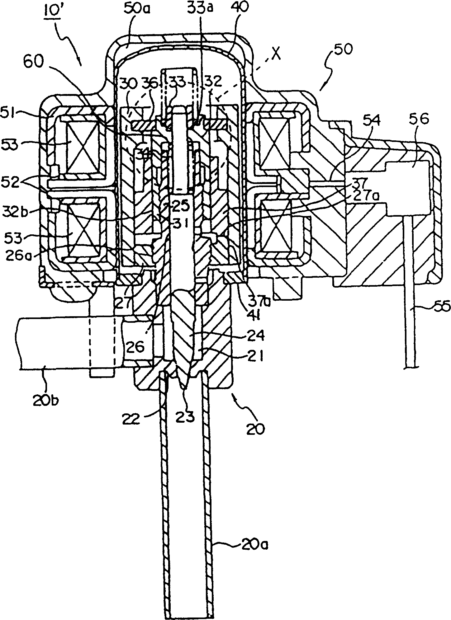
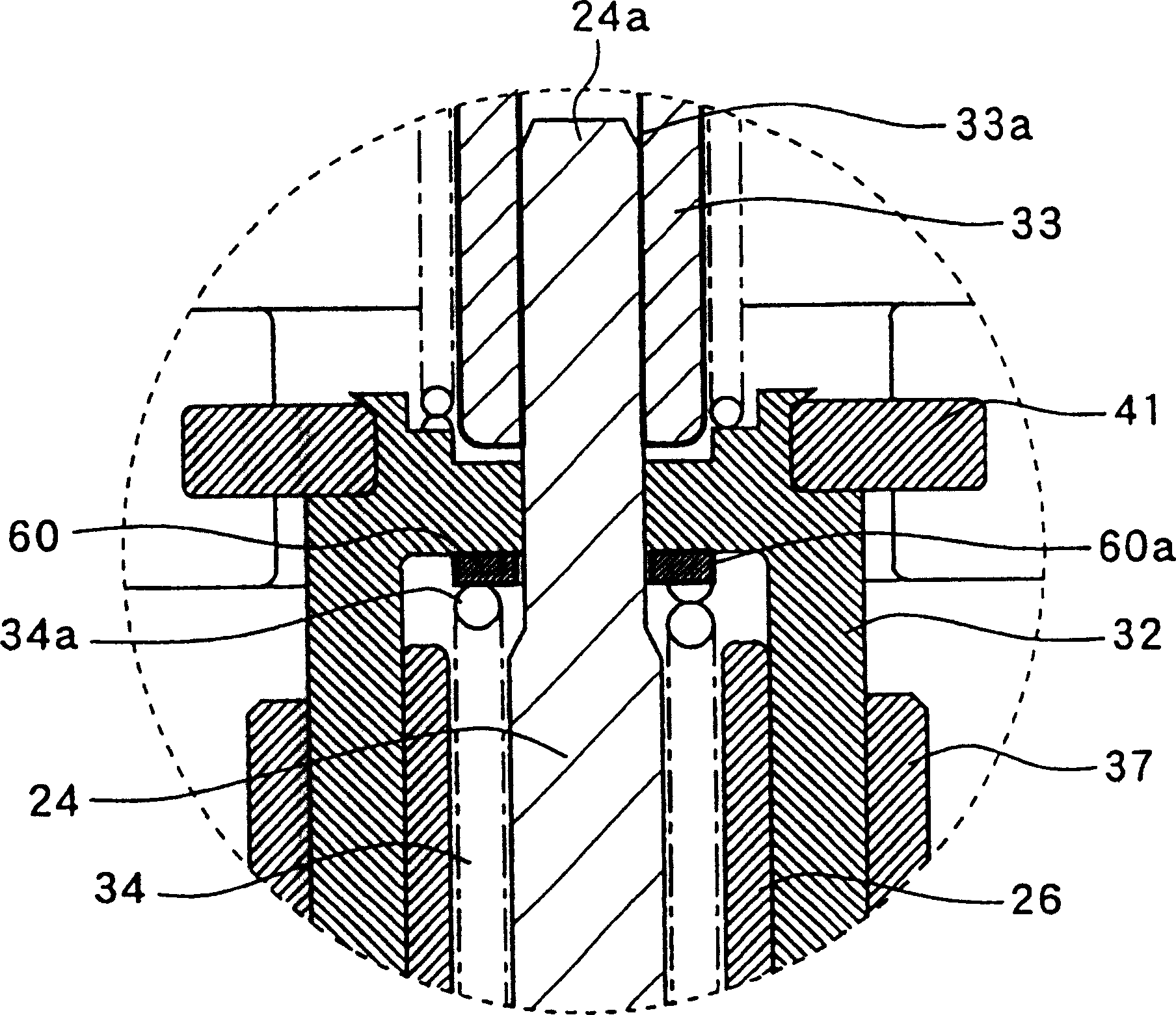
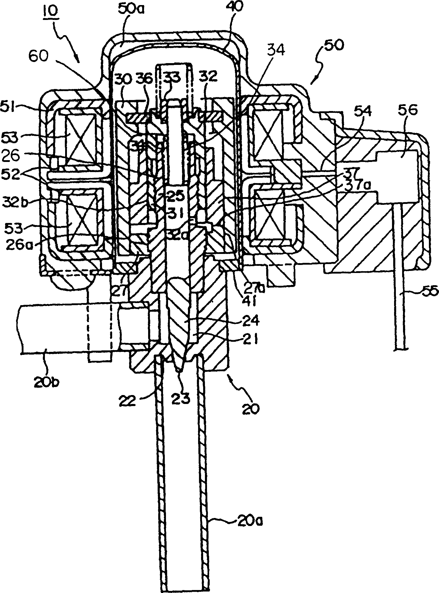
[0025] figure 1 It is a longitudinal sectional view of an embodiment of the electric valve 10' of the present invention, figure 2 yes figure 1 Enlarged view of part X of , based on these figures to illustrate. Below, in the description of the embodiments of the present invention, for figure 1 , 2 in and image 3 Components that are the same as those of the electric valve 10 in the shown known example are given the same reference numerals, and description thereof will be omitted.

[0026] As a feature of this embodiment, the surface of the thrust nut 33 is plated with nickel (Ni), or the surface is coated with nickel (Ni) plated metal including polytetrafluoroethylene (PTFE) as the plated layer 33 a. In addition, the metal plated layer 60a made of the same material as the surface of the thrust nut 33 is formed on the surface of the flat metal sheet 60 as well. Moreover, these treatments (the formation of the metallized layers 33a, 60a) can be carried out on the entire s...


PUM


Abstract

This motor operated valve comprises a valve main body 20 for adjusting a passing flow rate by a valve element 23 kept into contact with and separated from a valve seat 22 in a valve chamber 22 by a valve shaft 24, a can 40 incorporating a rotor 30 fixed to the valve main body 20 for bringing the valve element 23 into contact with the valve seat 22 or separated therefrom, and a stator 50 externally fitted to the can 40 for rotating and driving the rotor 30. The valve shaft 40 is slidably mounted on the push nut 33 and the flat washer 60. Plating layers 33a, 60a having the lubricating property are formed on the push nut 33 and the flat washer 60. The plating layer 33a is composed of a material including polytetrafluoroethylene.

Description

technical field [0001] The present invention relates to an electric valve installed and used in an air conditioner, a refrigerator, etc., and particularly relates to an electric valve in which fatigue resistance and lubricity of a sliding member constituting a valve shaft of a movable part are improved. Background technique [0002] At present, such electric valves used in air conditioners, refrigerators, etc. have the function of adjusting the fluid flow rate of refrigerants, etc., and generally have: a valve body including a valve chamber and a valve seat; The upper part of the main body is a bottomed cylindrical casing, a rotor is built inside the casing, and a stator having a through hole in the center is embedded outside the casing. [0003] image 3 A longitudinal sectional view of an electric valve 10 described in Patent Document 1 is shown. The electric valve 10 has: a valve body 20 that adjusts the flow rate of the refrigerant through the valve body 23 that is in c...

Claims


Application Information

Patent Timeline
Patent Type & Authority Applications(China)
IPC IPC(8): F16K31/04F16K1/00F25B41/04
CPCF16K31/04F25B2600/2521F25B41/20
Inventor 原田贵雄菅沼威
Owner FUJIKOKI MFG CO LTD
Why Eureka
Try Eureka