Capacitance detector, method of detecting capacitance, and fingerprint sensor

A capacitance detection and sensor technology, which is applied in the direction of converting sensor output, using electromagnetic/magnetic devices to transmit sensing components, electromagnetic measuring devices, etc.

Inactive Publication Date: 2005-02-09
ALPS ALPINE CO LTD
View PDF3 Cites 25 Cited by
  • Summary
  • Abstract
  • Description
  • Claims
  • Application Information

AI Technical Summary

Problems solved by technology

For this reason, there is a problem: it is very difficult to stably form a reference capacitor Cr that requires almost the same capacitance value as the detection object capacitor Cs without error, because the detection signal is affected by changes in the reference capacitor Cr, etc., and cannot be obtained. Detection signal with sufficient S / N ratio
[0007] Further, the existing problem is: for a matrix sensor, a plurality of switched capacitor circuits and reference capacitors Cr must be respectively connected to multiple row wirings; There is a disordered deviation between Cr, and it is difficult for each reference capacitor to be used as a reference capacitor in the entire detection system.

Method used


Image

  • Capacitance detector, method of detecting capacitance, and fingerprint sensor
  • Capacitance detector, method of detecting capacitance, and fingerprint sensor
  • Capacitance detector, method of detecting capacitance, and fingerprint sensor

Examples


no. 1 approach

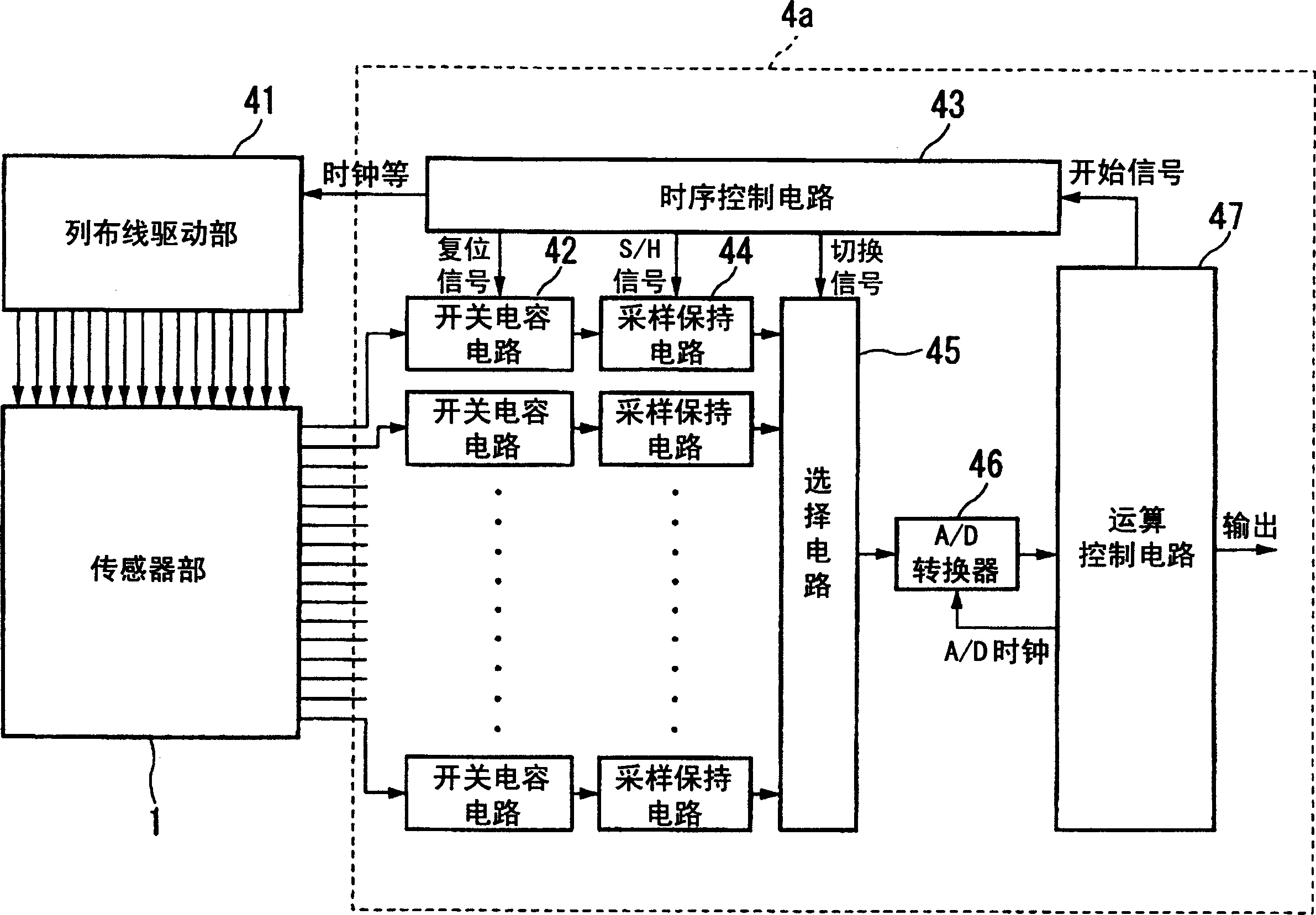
[0034] figure 1 It is a block diagram of the overall configuration of the first embodiment of the present invention. In the figure, a column wiring driving unit 41 (column wiring driving means) sequentially outputs signals that rise and fall with respect to a specific potential to each of the column wirings of the sensor unit 1 . When there is no output signal, it is kept at ground potential. Output signals from the wiring lines of each row of the sensor unit 1 are input to the capacitance detection circuit 4a.

[0035] The capacitance detection circuit 4a receives the output signal of the sensor unit 1, and detects the capacitance at each intersection of the column wiring and the row wiring. The internal function of the capacitance detection circuit 4a will be described below. Switched capacitor circuits 42, 42, . . . are connected to each row wiring. The switched capacitor circuits 42, 42, . The sampling memory circuits 44 , 44 . . . hold the output signals of the swit...


PUM


Abstract

A capacitance detector, used in an area sensor having a matrix of detection lines, detects minute capacitances near intersections of a plurality of column lines and a plurality of row lines. The capacitance detector includes a column-line driver for outputting to the column lines a signal that rises in response to a first voltage and then falls in response to a second voltage; a row-voltage outputter for outputting a third voltage corresponding to a current for charging the capacitance at each of the intersections when the column lines are driven by the first voltage and for outputting a fourth voltage corresponding to a current for discharging the capacitance at each of the intersections when the column lines are driven by the second voltage; and a calculator for calculating the difference between the third voltage and the fourth voltage. The difference is calculated at each of the intersections.

Description

technical field [0001] The invention relates to a capacitance detection circuit and a detection method for detecting tiny capacitance and a fingerprint sensor applying the method. Background technique [0002] In the past, as the most promising fingerprint sensor in biometric technology (biometric recognition technology), column wiring and row wiring were formed at a given interval on two thin film surfaces, and the wiring was arranged to face each other at a given interval by intervening an insulating film or the like. Pressure-sensitive capacitive sensors formed from thin films are under development. In this pressure-sensitive capacitive sensor, when a finger is placed, the shape of the film is deformed according to the shape of the fingerprint, and the interval between the column wiring and the row wiring changes according to the position, and the shape of the fingerprint is detected as the capacitance at the intersection of the column wiring and the row wiring. In this ...

Claims


Application Information

Patent Timeline
Patent Type & Authority Applications(China)
IPC IPC(8): G01B7/28A61B5/117G01D5/241G01R27/26G06K9/00G06T1/00
CPCG01D5/2417G06K9/0002G06V40/1306G01R27/26
Inventor 梅田裕一斋藤润一
Owner ALPS ALPINE CO LTD
Why Eureka
Try Eureka