
Ultra-low flying height slider and design method thereof

A technology of floating height and slider, which is applied in the direction of instruments, calculations, computers, etc., and can solve problems such as slider head and/or magnetic recording disk damage, head/disk contact, etc.

Inactive Publication Date: 2010-04-14
SAE MAGNETICS (HK) LTD
View PDF3 Cites 0 Cited by
  • Summary
  • Abstract
  • Description
  • Claims
  • Application Information

AI Technical Summary

Problems solved by technology

As mentioned above, one problem with low flying heights is that there is a greater risk of head / disk contact, which could lead to damage to the slider head and / or magnetic recording disk

Method used


Image

  • Ultra-low flying height slider and design method thereof
  • Ultra-low flying height slider and design method thereof
  • Ultra-low flying height slider and design method thereof

Examples


Embodiment Construction

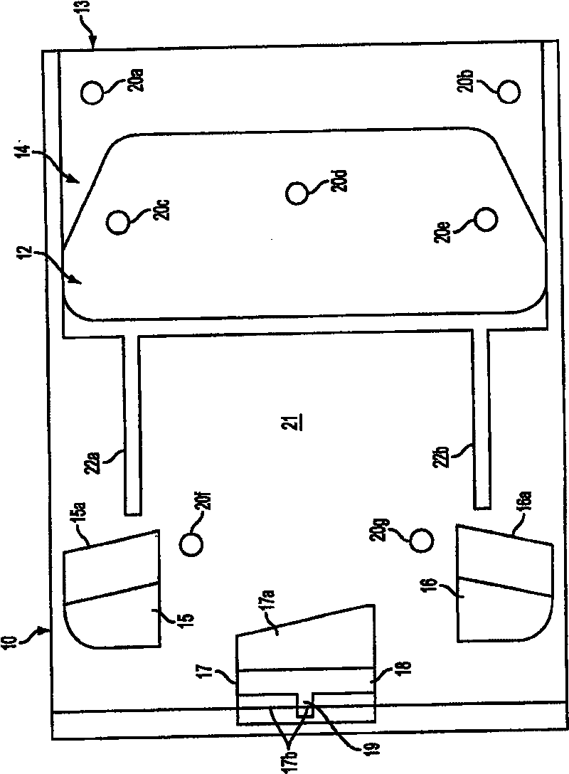
[0021] image 3 is a bottom plan view of the slider 10 for a low pressure slider according to an embodiment of the present invention. To illustrate specific features of ABS described below, it should be understood that the entire slider body, not shown, may be made of a base material such as Al 2 o 3 TiC composition. exist image 3 The slider 10 shown in includes a front air bearing surface 12 . The air bearing surface is marked off from the leading edge 13 of the slider 10 by a front step 14 . In this particular embodiment, the front step 14 has a depth relative to the front air bearing surface. In this particular embodiment, the depth is between 2 and 10 microinches. Double-sided air bearing surfaces 15 , 16 are provided at the inner and outer edges of the slider 10 . Although these two surfaces are provided, the invention is not limited to this number. Each of the air bearing surfaces 15, 16 comprises a secondary structure 15a, 16b respectively at a lower level. In...


PUM


Abstract

A subambient pressure air bearing slider for disk drives and the like is presented where features of the slider are modular, in that certain parameters of the slider can be modified independently of one another. In one example, lateral dimensions and placement of side and trailing air bearing surfaces can be used to control flying height sensitivity due to crowning in the slider. Longitudinal dimensions of the side air bearing surfaces can be used to control flying height sensitivity due to camber in the slider body. Low-profile members (e.g., ones that do not form air bearing surfaces) may beused to control the dimensions of the subambient pressure region to control overall flying height.

Description

technical field [0001] This invention relates to the design of air bearing sliders for disk drives. More particularly, the present invention relates to the modular design of slider air bearing surfaces in order to achieve ultra-low flying heights. Background technique [0002] Disk drives are general information storage devices that basically consist of a set of spinning disks that are accessed by magnetic read-write elements. These data transfer elements, often referred to as transducers, are typically supported by and embedded within a slider body that is placed in relatively close proximity over individual data tracks formed on the disk, for read and write operations. In order to properly position the transducer with respect to the disk surface, the air bearing surface (Air bearing surface, hereinafter referred to as ABS) formed on the slider body is subjected to a flowing air flow, which provides sufficient lift force so that the slider and transducer "floats" on the ...

Claims


Application Information

Patent Timeline
Patent Type & Authority Patents(China)
IPC IPC(8): G11B21/21G11B5/60G06F15/173
CPCG11B5/6005G11B5/6082G11B21/21
Inventor E·T·查
Owner SAE MAGNETICS (HK) LTD
Learn More