Screw electric inductor

A technology of inductors and spiral shapes, applied in the field of spiral inductors, can solve problems such as Q reduction, inability to use high-frequency inductors, and increased capacitance

Inactive Publication Date: 2005-02-09
ALPS ALPINE CO LTD
View PDF1 Cites 3 Cited by
  • Summary
  • Abstract
  • Description
  • Claims
  • Application Information

AI Technical Summary

Problems solved by technology

[0008] However, if the interval 53 is narrowed, the capacitance (capacity) generated between adjacent conductors 52 may increase, and the self-resonant frequency may be significantly lowered, so that it cannot be used as a high-frequency inductor.
[0009] Therefore, the conductors 52 are formed with the intervals 53 slightly enlarged, but since the intervals 53 of the overall spiral shape are large, the coupling between adjacent conductors 52 becomes thinner (thicker), thereby reducing the inductance, and the Q (Qualityfactor : quality factor) decreases
[0010] In the existing spiral inductors, since the conductors 52 with a certain width form a spiral shape with the same interval 53, there is a problem: due to the relationship between the capacitance and coupling between adjacent conductors 52, if the Q , the self-resonant frequency decreases, and if the self-resonant frequency increases, Q decreases

Method used


Image

  • Screw electric inductor
  • Screw electric inductor

Examples


Embodiment Construction

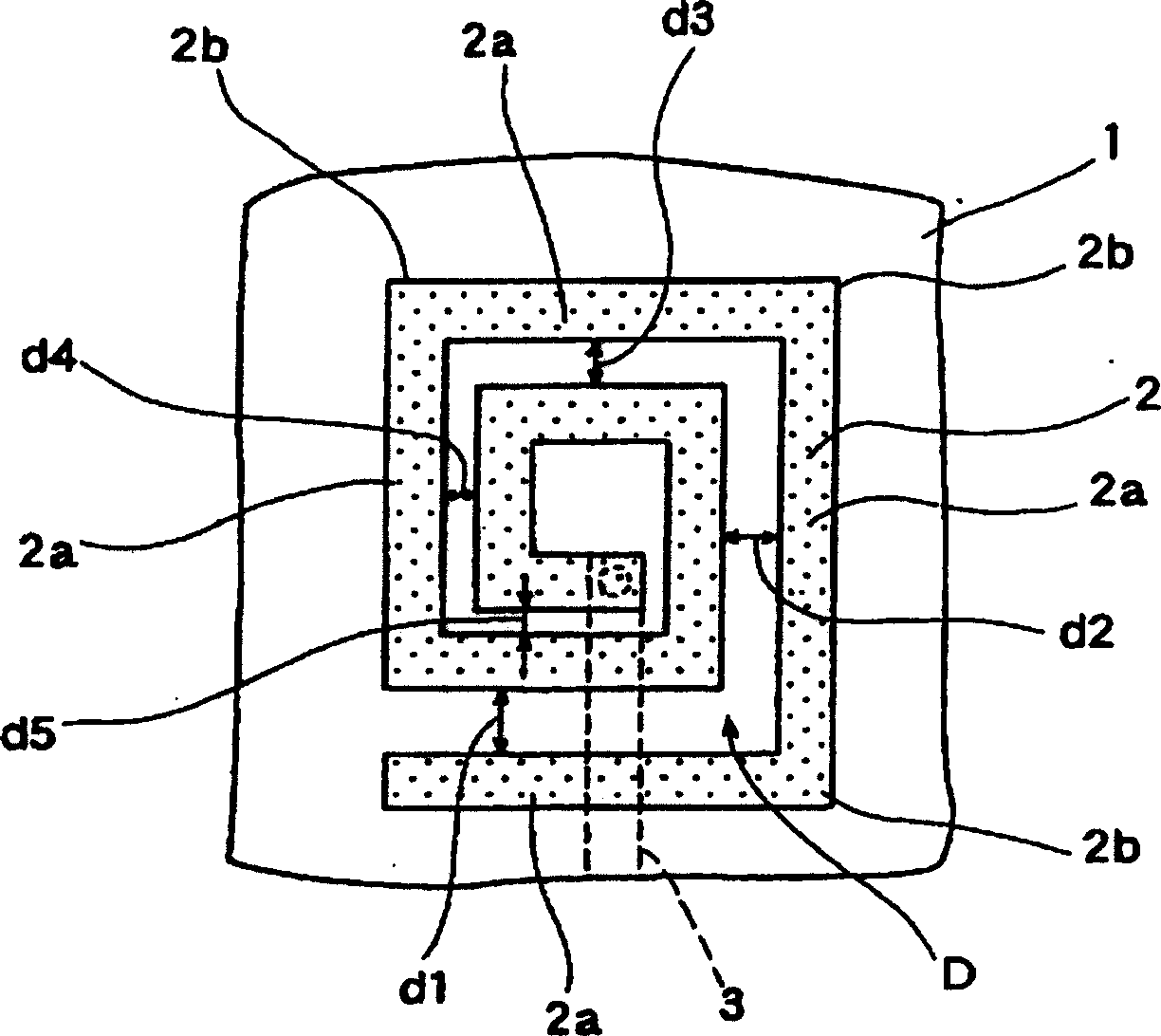
[0021] The drawings of the spiral inductor of the present invention will be described. figure 1 is a plan view of the spiral inductor of the present invention.

[0022] Next, according to figure 1 The structure of the spiral inductor of the present invention is described. On one side of a flat insulating substrate 1 such as alumina, a conductor 2 formed of a conductive pattern made of a thin film or the like is provided, and the conductor 2 is formed so that a gap D is maintained between adjacent conductors. of square (quadrilateral) swirl shapes.

[0023] In addition, an insulating substrate other than alumina may be used for the insulating substrate 1, and the conductor 2 may be formed by a method other than thin film printing or the like.

[0024] The entire conductor 2 is formed with a constant width (the same width), and the interval D is formed so as to become narrower from the outer side to the inner side of the spiral shape.

[0025] In addition, the interval D in...


PUM


Abstract

Provided is a spiral inductor capable of increasing the Q thereof as much as possible while suppressing the deterioration of a self resonance frequency as much as possible. The spiral inductor is provided with a flat sheet type insulating substrate 1, and a conductor 2 formed of a conductor pattern on at least one side of the insulating substrate 1 and arranged spirally while retaining an interval D between the neighboring conductive patterns so as to have a given width. The interval d5 of inside of the spiral shape is formed so as to be narrower than another interval d1 of the outside of the spiral shape whereby the winding diameter of the conductor 2 positioned at the inside of the spiral shape becomes big and connection between the conductors becomes dense, thereby increasing an inductance and, as a result, the Q (Quality factor) can be increased.

Description

technical field [0001] The invention relates to a spiral inductor suitable for various electronic circuit units or electronic circuit modules. Background technique [0002] figure 2 It is a drawing explaining the conventional spiral inductor, and is a plan view of the conventional spiral inductor. [0003] Below, according to figure 2 The structure of a conventional spiral inductor is described. On one side of a flat insulating substrate 51, a conductor 52 formed of a conductive pattern is provided. shape). [0004] The entire conductor 52 is formed with a constant width (the same width), and the conductor 52 is arranged such that the entire interval 53 from the outer side to the inner side of the spiral shape has the same size. [0005] Further, on the other side of the insulating substrate 51, a wiring pattern 54 is provided, and the conductor 52 located at the inner end of the spiral shape is connected to one end of the wiring pattern 54 through a through hole (connec...

Claims


Application Information

Patent Timeline
IPC IPC(8): H01F17/00
Inventor 植田和彦
Owner ALPS ALPINE CO LTD
Why Eureka
Try Eureka