Cross Lap-forming device

A cross-lapper and laying technology, which is applied in the direction of rolling mechanism, textile and papermaking, fiber processing, etc., can solve problems such as affecting the quality of non-woven fabrics

Inactive Publication Date: 2014-12-03
TRUETZSCHLER GMBH & CO KG
View PDF0 Cites 1 Cited by
  • Summary
  • Abstract
  • Description
  • Claims
  • Application Information

AI Technical Summary

Problems solved by technology

However, breathable belts are disadvantageous just in the laying area of ​​the fiber web on the output belt of the cross-laying machine, because the entrained air which flows out vertically through the mating belt causes the edge of the fiber web to curl. curling or folding, which adversely affects the quality of the produced nonwovens

Method used


Image

  • Cross Lap-forming device
  • Cross Lap-forming device
  • Cross Lap-forming device

Examples


Embodiment Construction

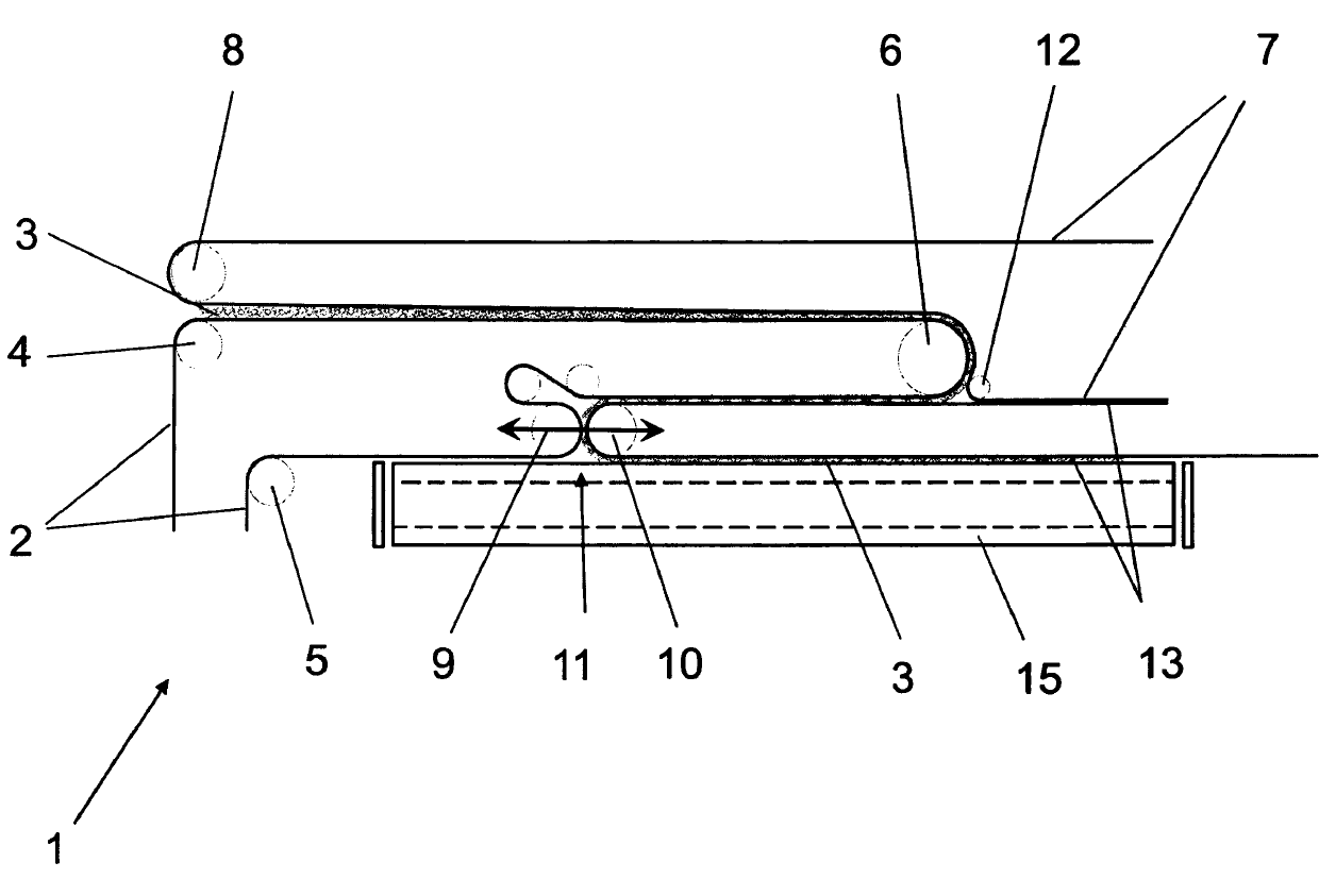
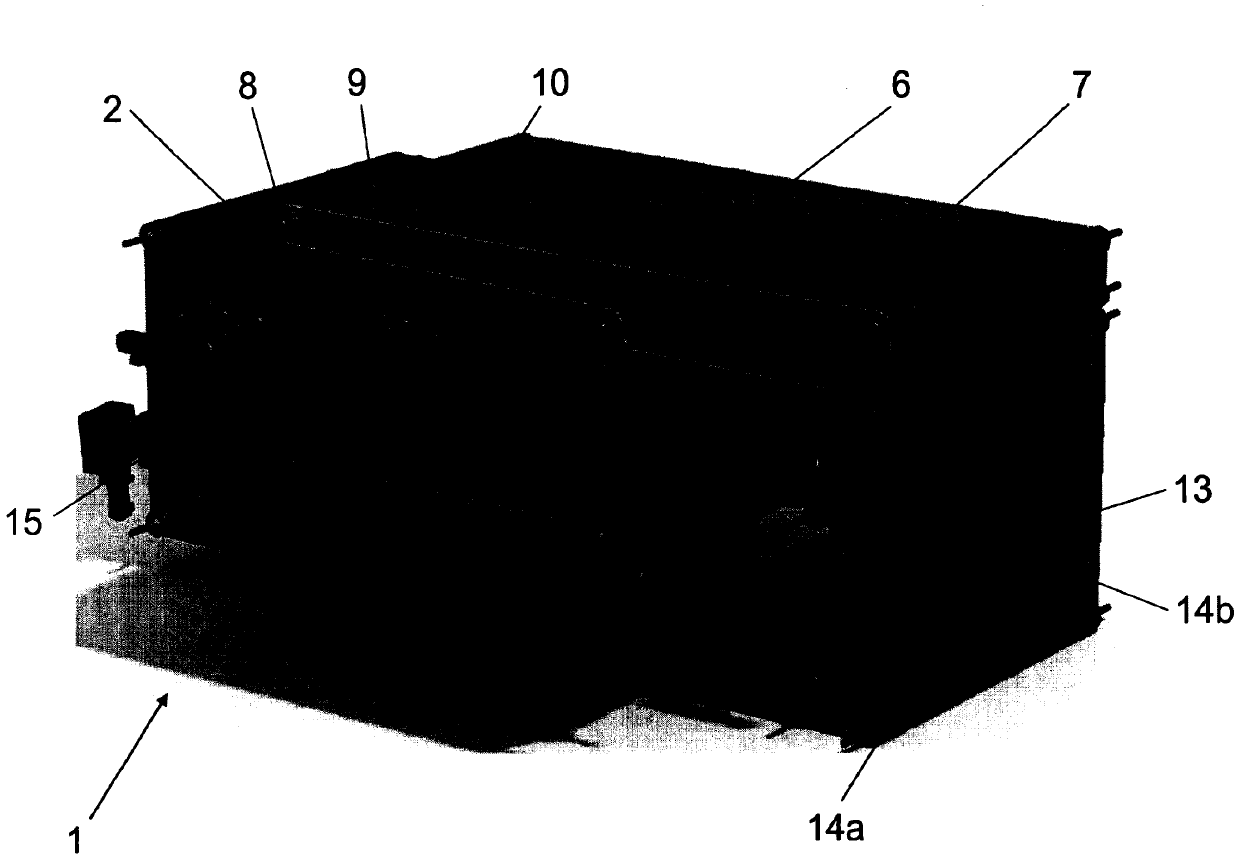
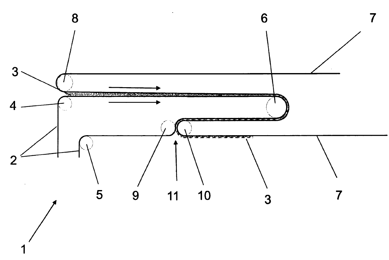
[0022] exist figure 1 The principle of the crosslapper is shown by way of example and only schematically. The fiber web 3 is conveyed from a carding device (not shown) onto the input belt 2 of the crosslapper 1 . Arranged inside the crosslapper 1 is an upper frame, of which only deflection rollers 6 can be seen in the illustration. Furthermore, the crosslapper 1 has a laying frame, from which a depositing roller 10 for the mating belt 13 and a depositing roller 9 for the input belt 2 are shown. Between the deposit roller 10 of the mating belt 13 and the deposit roller 9 of the feed belt 2 a so-called deposit gap 11 is arranged, from which the fiber web 3 emerges and is deposited under the deposit support. The output belt 15 on. Depending on the direction of travel, the two deposit rollers 9, 10 undertake the task of depositing the fiber web 3 perpendicularly to the current direction of travel on the delivery belt 15 arranged below the deposit frame and folding it there. . ...


PUM


Abstract

The invention relates to a cross lap-forming device to form a non-woven fabric through several layers of fibrous webs, the cross lap-forming device comprises at least one endlessly revolving input belt (2), which conveys the fibrous webs (3) from an input area of the cross lap-forming device (1) to a laying gap (11) of a laying support, the cross lap-forming device also comprises another endlessly revolving belt which cooperates with the laying support, and the endlessly revolving belt and the input belt (2) lay the fibrous webs (3) on an output belt (15). The invention is characterized in that the endlessly revolving belt is available as an air-permeable belt having at least one air-impermeable edge.

Description

technical field [0001] The invention relates to a crosslapper for forming nonwovens from multilayer webs. Background technique [0002] For the production of multilayer nonwovens, carding lines with subsequent crosslappers are usually used. In a carding device, fiber tufts are fed on the input side, the fiber tufts are debonded to individual fibers and are output on the output side as an unconsolidated two-dimensional fabric—fibrous web. [0003] In order to make full use of the available carding energy, it is necessary to increase the web speed in the subsequently arranged crosslapper. Here, however, high centrifugal forces occur at the deflection rollers of the depositing belt, which significantly reduce the quality properties of the fiber web as a function of the running direction and belt speed. [0004] For this purpose, a stabilizing web guide is known, wherein an embodiment is provided with a cover belt so that the incoming fiber web runs from the input area of ​​th...

Claims


Application Information

Patent Timeline
Patent Type & Authority Applications(China)
IPC IPC(8): D04H1/74
CPCD01G25/00
Inventor 莱因霍尔德·多林海科·思科弩特霍斯特·腾尼斯斯文·汤姆森施特凡·霍尔特肯
Owner TRUETZSCHLER GMBH & CO KG
Why Eureka
Try Eureka