Tooth edge float valve

A float valve and tooth edge technology, applied in the field of float valves, can solve the problems of uneven gas holdup and bubble size in the foam layer, unsatisfactory treatment efficiency of float valve trays, and tray pressure drop, etc., so as to reduce the liquid level drop. , The effect of increasing the gas-liquid contact area and increasing the processing capacity

Active Publication Date: 2008-01-09
CHINA PETROLEUM & CHEM CORP +1
View PDF1 Cites 2 Cited by
  • Summary
  • Abstract
  • Description
  • Claims
  • Application Information

AI Technical Summary

Problems solved by technology

[0009] In order to overcome the disadvantages of unsatisfactory treatment efficiency of the float valve tray, high tray pressure drop, uneven gas holdup rate and bubble size of the foam layer, and large liquid level drop in the prior art, the utility model provides a mass transfer Float valve for the float valve tray with high efficiency, low tray pressure, uniform gas holdup and bubble size in the foam layer, and small liquid level drop

Method used


Image

  • Tooth edge float valve
  • Tooth edge float valve
  • Tooth edge float valve

Examples


Embodiment 1

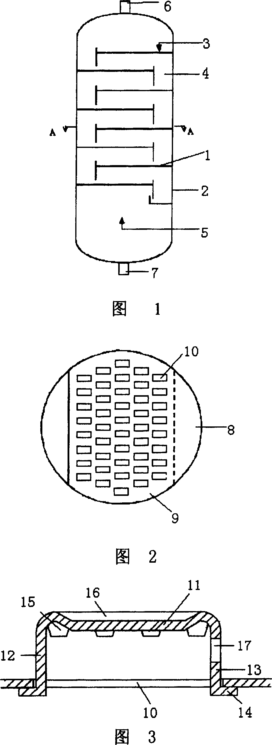
[0028] Referring to Fig. 1 and Fig. 2, several trays 1 equipped with tooth edge float valves according to the utility model are installed in the vertical tower 2 in sequence. Liquid is introduced from a liquid supply line 3 to the upstream end of the uppermost tray. Downcomers 4 direct liquid from the downstream end of a higher tray to the upstream end of an adjacent lower tray. The gas is introduced under the lowermost tray through the gas supply line 5, and the gas enters the liquid on the tray through the serrated float valve on the tray. The top of the vertical tower is provided with a gas discharge port 6, and the bottom is provided with a liquid discharge port 7. There is a liquid receiving area 8 on each tray, which accepts the liquid from the downcomer 4, and the liquid comes out of the downcomer 4 and falls into the liquid receiving area 8, and then turns to flow to the bubbling area 9 provided with tooth edge float valves. . A valve hole 10 is opened in the bubbli...

Embodiment 2

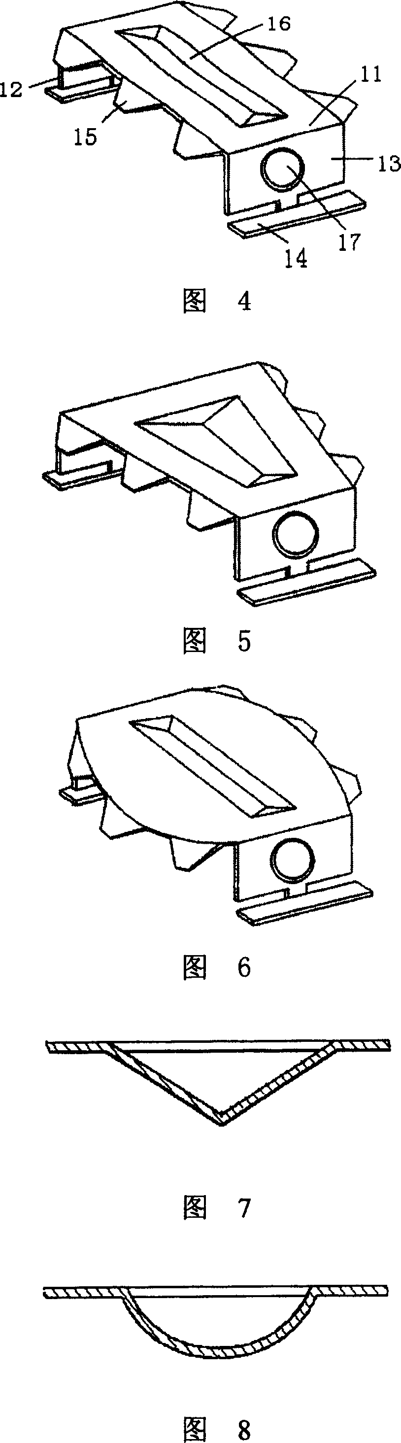
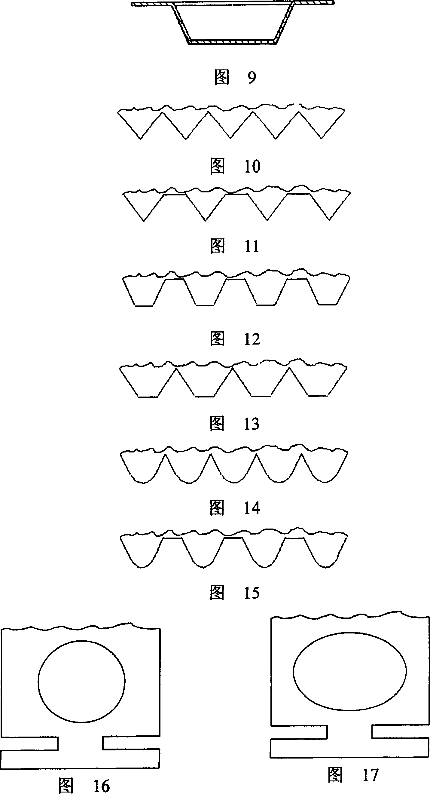
[0035] Referring to FIGS. 3 and 4 , a wedge-shaped groove 16 is provided on the valve cover 10 . The wedge-shaped groove 16 can guide the flow of gas to both sides of the valve hole of the upper tray, avoiding the formation of air flow vortex under the float valve, reducing the back mixing of liquid and the resistance of gas passing through the float valve. The shape of the cross section of the wedge-shaped groove 16 can be varied, such as V-shape, arc shape, inverted trapezoid shape, etc. as shown in FIGS. 7-9 .

[0036] The rest of the structure and implementation are the same as in Embodiment 1.

Embodiment 3

[0038]Referring to Fig. 3 and Fig. 4, a liquid guide hole 17 is opened on the back liquid valve leg 13, and the liquid guide hole 17 can push the liquid to flow to the outlet weir through the gas, reducing the drop of liquid level and reducing the return of liquid. mix. The liquid guide hole 17 is opened on the back liquid valve leg. When the gas volume passing through the float valve is small, the float valve does not float, and the liquid guide hole 17 is below the tray. Therefore, the opening of the liquid guide hole 17 will not raise the float. The lower operating limit of the valve tray. The shape of the liquid guide hole 17 can be various, such as circle, ellipse, rectangle, trapezoid, triangle, rhombus, etc. as shown in FIGS. 16-21 .

[0039] The rest of the structure and implementation are the same as in Embodiment 1.


PUM


Abstract

The tooth edge float valve includes tabulated valve cover, liquid facing valve leg on one end of the valve cover and in the upstream position, liquid backing valve leg on the other end of the valve cover and in the downstream position, and valve feed fixed separately to the lower ends of the liquid facing valve leg and the liquid backing valve leg. The valve cover has downward bending toothed structures in the sides and the downward bending toothed structures can reduce the bubble diameter, raise the stability of the foam layer and avoid the direct spray of gas and liquid. In addition, the valve cover is provided with wedged slot to avoid the formation of gas flow eddy below the float valve, decrease liquid back mixing and lower the gas resistance of the float valve; and the liquid backing valve leg is provided with liquid guide hole for gas to drive liquid towards the outlet dam so as to reduce the liquid surface fall and decrease liquid back mixing.

Description

(1) Technical field [0001] The utility model relates to a float valve used for a float valve tray. (2) Background technology [0002] Float valve tray has the advantages of large operating flexibility, small mist entrainment, less liquid leakage, large processing capacity and high mass transfer efficiency, and is widely used in chemical industry, petroleum industry and pharmaceutical industry. At present, F1 valve trays and strip valve trays are commonly used in industrial production. The F1 float valve rotates continuously under the action of the air flow, causing the valve foot and the valve hole to wear, and the float valve is easy to get stuck or fall off, which affects the fluid mechanics and mass transfer performance of the tray, and even has to be shut down for maintenance. During the operation of the F1 valve tray, the air flow is sprayed from around the float valve, and the liquid phase on the plate is back mixed, which reduces the mass transfer efficiency of the t...

Claims


Application Information

Patent Timeline
Patent Type & Authority Patents(China)
IPC IPC(8): B01D3/20
Inventor 姚克俭王良华俞晓梅
Owner CHINA PETROLEUM & CHEM CORP
Why Eureka
Try Eureka