
Horn switch gear and airbag system

A switch device and speaker technology, applied in the direction of electric switch, signal device, sound signal device, etc., can solve the problem of high difficulty in assembly operation, and achieve the effect of good assembly operability and easy determination

Inactive Publication Date: 2005-02-09
TAKATA CORPORATION
View PDF2 Cites 15 Cited by
  • Summary
  • Abstract
  • Description
  • Claims
  • Application Information

AI Technical Summary

Problems solved by technology

If the contact parts are separately arranged in this way, the assembly work is difficult because the position between them must be determined with high precision.

Method used


Image

  • Horn switch gear and airbag system
  • Horn switch gear and airbag system
  • Horn switch gear and airbag system

Examples


Embodiment Construction

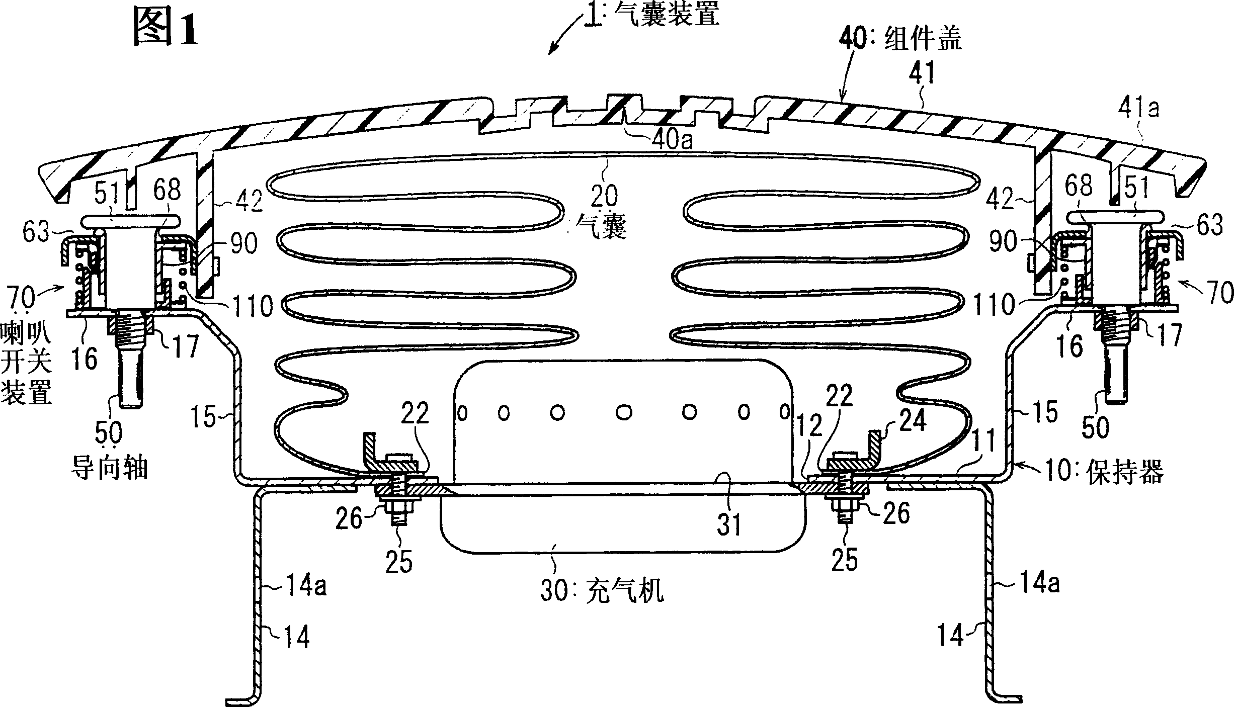
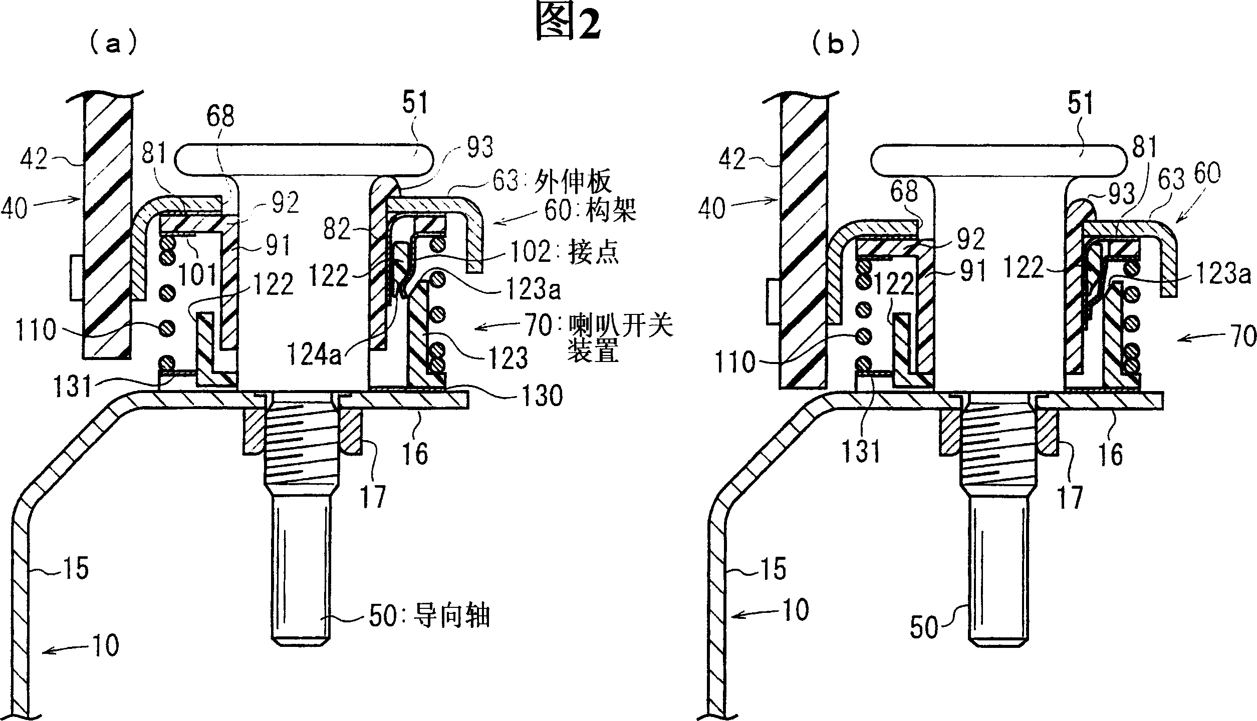
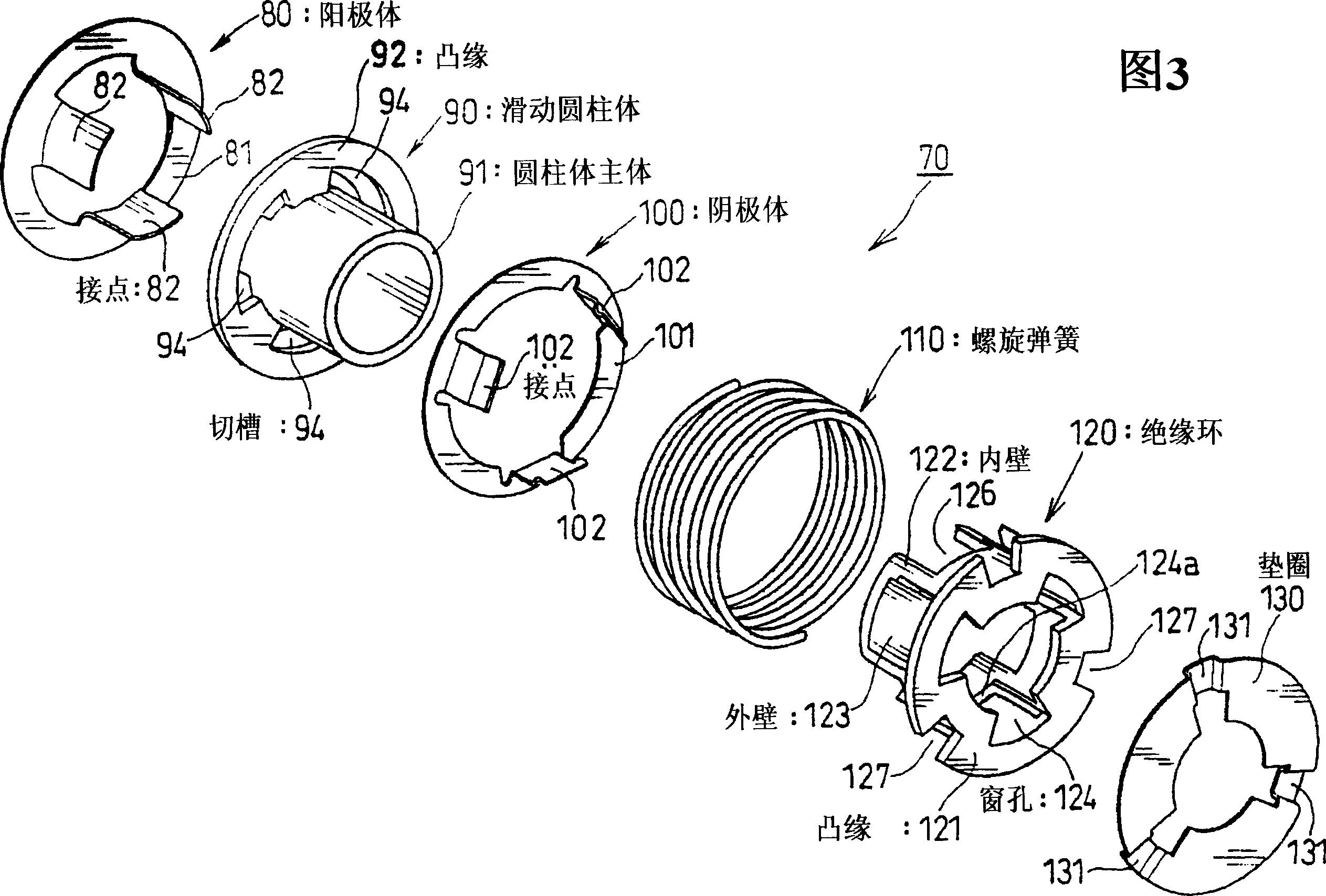
[0041] Embodiments are described below with reference to the drawings. FIG. 1 is a cross-sectional view of an airbag device provided with a horn switch device in an embodiment. Fig. 2(a), (b) are partial enlarged views of the horn switch in Fig. 1 . Fig. 3, 4 is the disassembled view of this horn switch device, and Fig. 3, 4 is the situation that mutually sees from the opposite direction. Fig. 5 is an exploded perspective view of the airbag device. In addition, FIG. 2(a) shows the "unpressed" state where the assembly cover 40 is not pressed, and Fig. 2(b) shows the "pressed assembly cover state" in which the horn sounds after the assembly cover 40 is pressed.

[0042] The airbag device 1 is an airbag device for a driver's seat provided in the center of a steering wheel. The structure of this airbag device 1 is provided with a retainer 10 made of metal, an airbag 20 mounted on this retainer 10 with an airbag mounting ring 24, an inflator 30 for inflating the airbag 20, and a...


PUM


Abstract

Provided is a horn switching device in which mutual positioning of contacts is easy and in which fitting to an airbag device is easy. The horn switching device 70 is installed between a frame 60 mounted on a module cover 40 and a retainer extension part 16. Contacts 82, 102 are both installed on the module cover 40 side. Until the module cover 40 is pushed, an inner wall 122 is interposed between the contacts 82, 102, and the contacts 82, 102 are separated from each other. If the module cover 40 is pushed, the contacts 82, 102 also move downward, and the contact 102 is pushed inward by a gradient 123a, and the contacts 82, 102 are contacted with each other. By this, the horn sounds.

Description

technical field [0001] The present invention relates to a horn switch, in particular to a horn switch device which is installed on an airbag device and turns the unit cover or the entire airbag device into an ON state after being pressed. Furthermore, the present invention relates to an airbag device provided with the horn switch device. Background technique [0002] As an airbag device for the driver's seat installed in the steering wheel of an automobile, there is a device that makes the horn sound when the horn switch is turned ON when the cover of the airbag is pressed. Patent Documents 1 and 2 below disclose devices in which the horn is turned ON after the airbag device is pressed and the module cover is pressed. [0003] [Patent Document 1] JP-A-10-100832 [0004] [Patent Document 2] JP-A-2001-114057 [0005] In the above-mentioned existing horn switch devices, one contact part is installed on the assembly cover, and the other is installed on the holder. If the con...

Claims


Application Information

Patent Timeline
IPC IPC(8): B60R16/027B60Q5/00B60R21/20B60R21/203B62D1/10H01H1/14H01H13/08
CPCB60R21/21658B60Q5/003B60R21/2037
Inventor 杉本真一
Owner TAKATA CORPORATION
Learn More