Axial radial-flow type turbine

一种辐流式、涡轮机的技术,应用在反作用式发动机、机械设备、发动机元件等方向,能够解决压力分布变形、水力效率损失等问题

Inactive Publication Date: 2005-02-16
KK TOSHIBA
View PDF5 Cites 0 Cited by
  • Summary
  • Abstract
  • Description
  • Claims
  • Application Information

AI Technical Summary

Problems solved by technology

[0010] In particular, secondary flows other than streamlines are known to distort the pressure distribution on the blades and lead to a loss of hydraulic efficiency

Method used


Image

  • Axial radial-flow type turbine
  • Axial radial-flow type turbine
  • Axial radial-flow type turbine

Examples


Embodiment Construction

[0023] Refer below Figures 1 to 3 The first embodiment according to the present invention is explained.

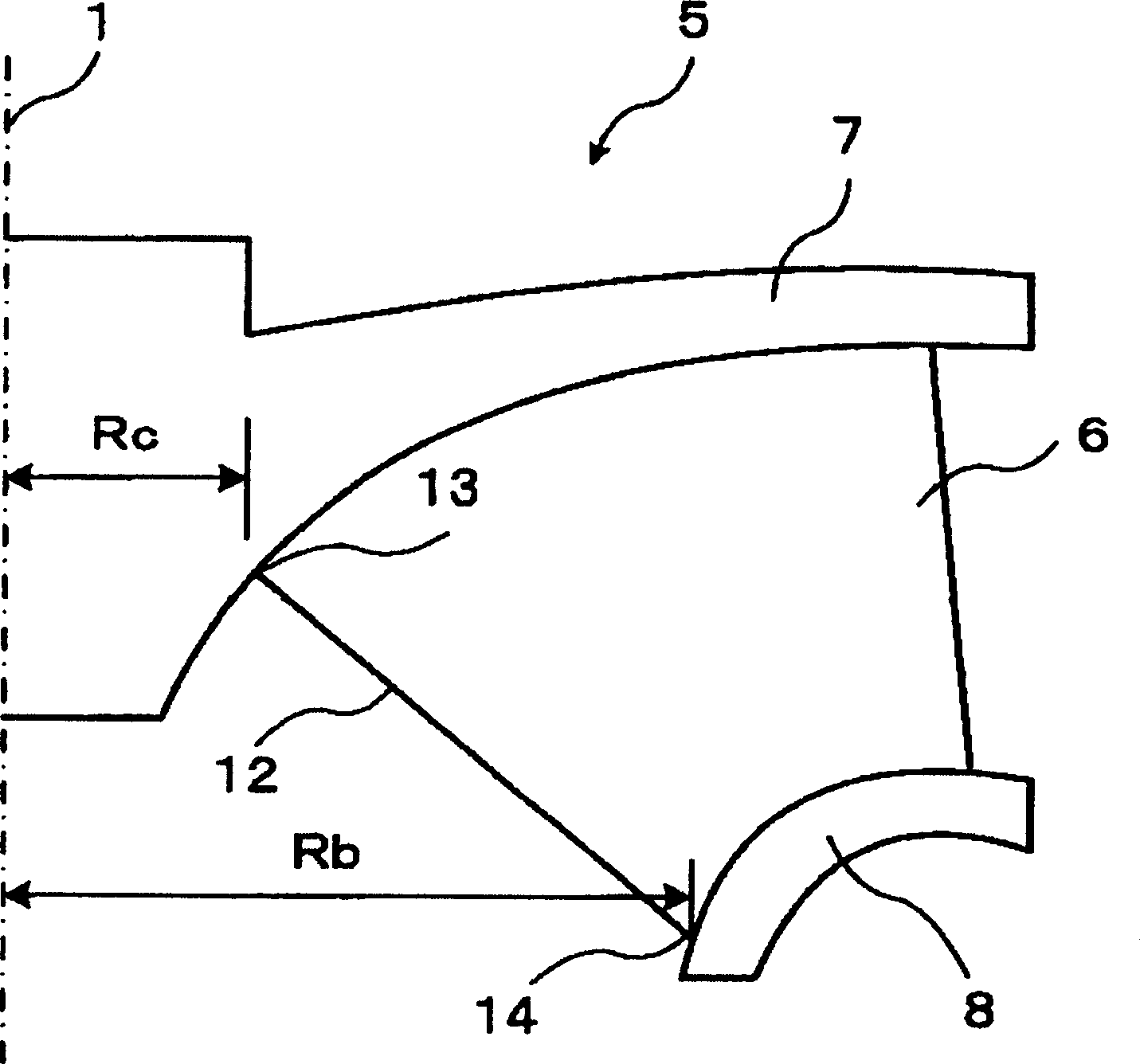
[0024] figure 1 It is a half sectional view including the central axis of an axial radial turbine runner according to the first embodiment of the present invention. Since the rotor of an axially radial turbine rotates about a central axis (also called the axis of rotation), the figure 1 Half of the figure is omitted in , since it is a symmetrical profile.

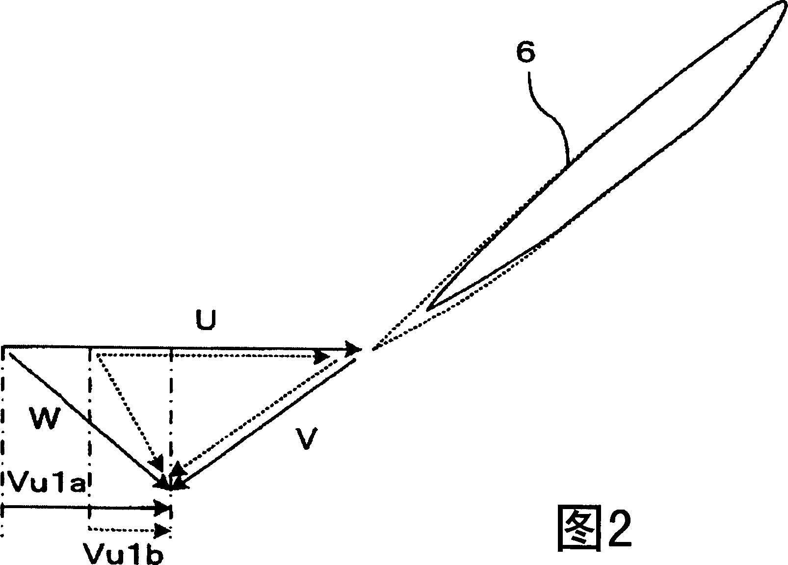
[0025] Such as figure 1 As shown, an axial radial turbine runner 5 includes an upper crown 7 , a lower ring 8 and a plurality of runner blades 6 . The upper crown 7 is connected to the rotation shaft at the rotation axis 1 . The runner blades 6 are arranged on the upper crown 7 along the circumference. exist figure 1 In , one of the runner blades 6 is shown as a projected profile on the meridian plane, which is the plane containing the axis of rotation 1 . A lower ring 8 is connected to the runner blades 6 and ...


PUM


Abstract

A Francis turbine has a rotating array of turbine blades rotating on a hub and enclosed within a rotating shroud. Each blade has a root, a tip, a leading edge and a trailing edge. The distance Rc between the axis of rotation (1) and the shroud (7), divided by the distance Rb between the axis of rotation (1) and the root end (14), is a ratio between 0.2 and 04.

Description

[0001] Cross References to Related Applications [0002] This application is based on and claims the benefit of priority from prior Japanese Patent Application No. 2003-291266 filed on August 11, 2003, the entire contents of which are hereby incorporated by reference. technical field [0003] The present invention relates to axially radial turbines for water turbines or pumps, and in particular to axially radial turbines with blades having improved shaped trailing edges. Background technique [0004] Axial radial turbines are used in hydroelectric machinery for generating electricity, including reversible pump turbines. [0005] A conventional radial radial turbine wheel is described in US Patent 4,479,757. Such a conventional radial radial turbine wheel includes blades whose inlet (leading edge) shape is curved from the lower ring side to the upper crown side in a direction opposite to the direction of rotation in which the turbine operates. [0006] Another conventional ...

Claims


Application Information

Patent Timeline
Patent Type & Authority Applications(China)
IPC IPC(8): F03B3/12F01D17/12F03B3/02F03B3/10
CPCY10S416/02Y02E10/223F03B3/125Y02E10/20
Inventor 榎本保之铃木敏暁黑泽贞男中村高纪
Owner KK TOSHIBA
Why Eureka
Try Eureka