Tandem blade type mixed-flow or radial-flow turbine
A mixed flow and radial flow technology, which is applied in the direction of gas turbine devices, blade support components, joint combustion mitigation, etc., can solve the problems of turbine efficiency reduction and internal flow complexity, etc., to reduce secondary flow, improve uniformity, and suppress flow separation. Effect
Inactive Publication Date: 2011-11-09
TSINGHUA UNIV
View PDF0 Cites 0 Cited by
- Summary
- Abstract
- Description
- Claims
- Application Information
AI Technical Summary
Problems solved by technology
Under the condition of pulsed intake, the turbine inlet angle of attack varies in a large range, the internal flow is more complicated, and large flow separation is prone to occur near the leading edge of the blade, which significantly reduces the turbine efficiency
Method used
View moreImage
Smart ImageViewing Examples
Examples
Embodiment approach
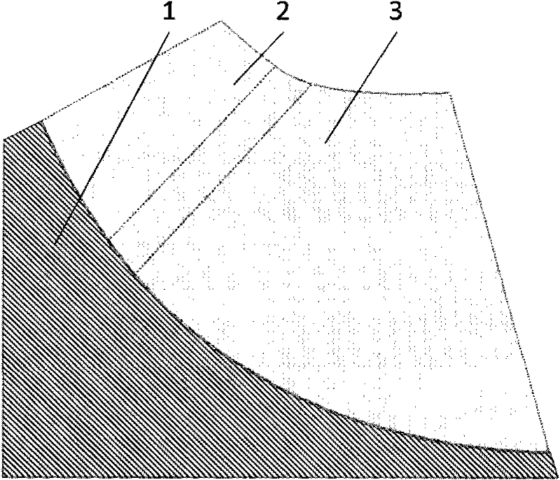
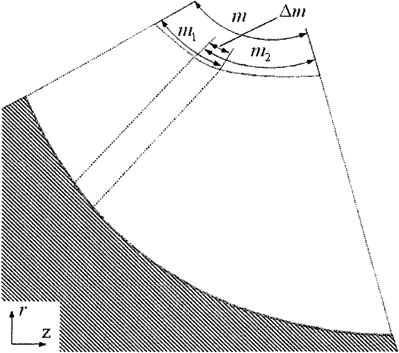
[0026] As shown in Figure 4(a), Figure 4(b) and Figure 4(c), the number of front row blades and rear row blades is 12, and the relative chord length of the front row blades is m 1 = M 1 / M=0.3, the relative chord length of the rear blades m 2 = M 2 / M=0.74, then Δm=ΔM / M=m-(m 1 +m 2 )=-0.04, tandem blade length coefficient Circumferential position coefficient flow position coefficient
Login to View More PUM
 Abstract
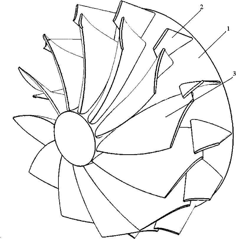
The invention relates to the technical field of blade type fluid machines, in particular to a tandem blade type mixed-flow or radial-flow turbine comprising a hub, front-row blades and back-row blades, wherein the ratio of the numbers of the tandem blade type front-row Z1 and the numbers of the back-row blades Z2 is 1:1 or 1:2, the ratio variation range of the lengths of the front-row and back-row blades is 0.1-0.5, the variation range of relative circumferential angles between the front edges of the back-row blades and the tail edges of the front-row blades is 0-2 pi / Z1, and the variation range of the distances between the tail edges of the front-row blades and the front edges of the back-row blades is -0.3 to 0.3 of the total blade chord length. By the airflow blowing-down function generated by a gap between the front-row blades and the back-row blades, the flow separation close to the front edges of the blades is restrained, the secondary flow is weakened, the efficient running range is enlarged, and the whole performance of the turbine under undersign conditions and pulse charging conditions is improved.
Description
technical field [0001] The invention relates to the technical field of vane type fluid machinery, in particular to a tandem vane type mixed-flow or radial-flow turbine applicable to the fields of diesel engines, gasoline engine superchargers, small gas turbines, expanders and the like. Background technique [0002] A turbine is a blade-type fluid machine that converts the energy of the working medium into mechanical energy for output. According to the flow direction of the working fluid in the turbine, it can be divided into axial flow, radial flow and mixed flow turbines. The structural feature of the radial turbine is that the working medium generally flows into the impeller in a radial direction and flows out in the axial direction. Compared with the axial flow turbine, it has the characteristics of compact structure, low manufacturing cost, high efficiency at low flow rate, large stage expansion ratio, etc. It is widely used in small and medium-sized power plants, turbo...
Claims
Login to View More Application Information
Patent Timeline
 Patent Type & Authority Patents(China)
IPC IPC(8): F01D5/04F02B39/00F02B37/00F02C6/12
CPCY02E20/14Y02T10/144Y02T10/12
Inventor 诸葛伟林陈理张扬军郑新前张树勇
Owner TSINGHUA UNIV
Features
- R&D
- Intellectual Property
- Life Sciences
- Materials
- Tech Scout
- Unparalleled Data Quality
- Higher Quality Content
- 60% Fewer Hallucinations
Learn More Browse by: Latest US Patents, China's latest patents, Technical Efficacy Thesaurus, Application Domain, Technology Topic, Popular Technical Reports.
© 2025 PatSnap. All rights reserved.Legal|Privacy policy|Modern Slavery Act Transparency Statement|Sitemap|About US| Contact US: help@patsnap.com


