Centrifugal pump having a radial impeller

A centrifugal pump and impeller technology, applied in the direction of pumps, components of pumping devices for elastic fluids, pump components, etc., can solve the problems of design cost, easy failure, etc., and achieve the effect of improving efficiency and reliable operation characteristics

Active Publication Date: 2019-07-19
KSB AG
View PDF7 Cites 0 Cited by
  • Summary
  • Abstract
  • Description
  • Claims
  • Application Information

AI Technical Summary

Problems solved by technology

[0006] This conventional disc design for axial thrust reduction is prone to failure and is often costly in its design

Method used


Image

  • Centrifugal pump having a radial impeller
  • Centrifugal pump having a radial impeller
  • Centrifugal pump having a radial impeller

Examples


Embodiment Construction

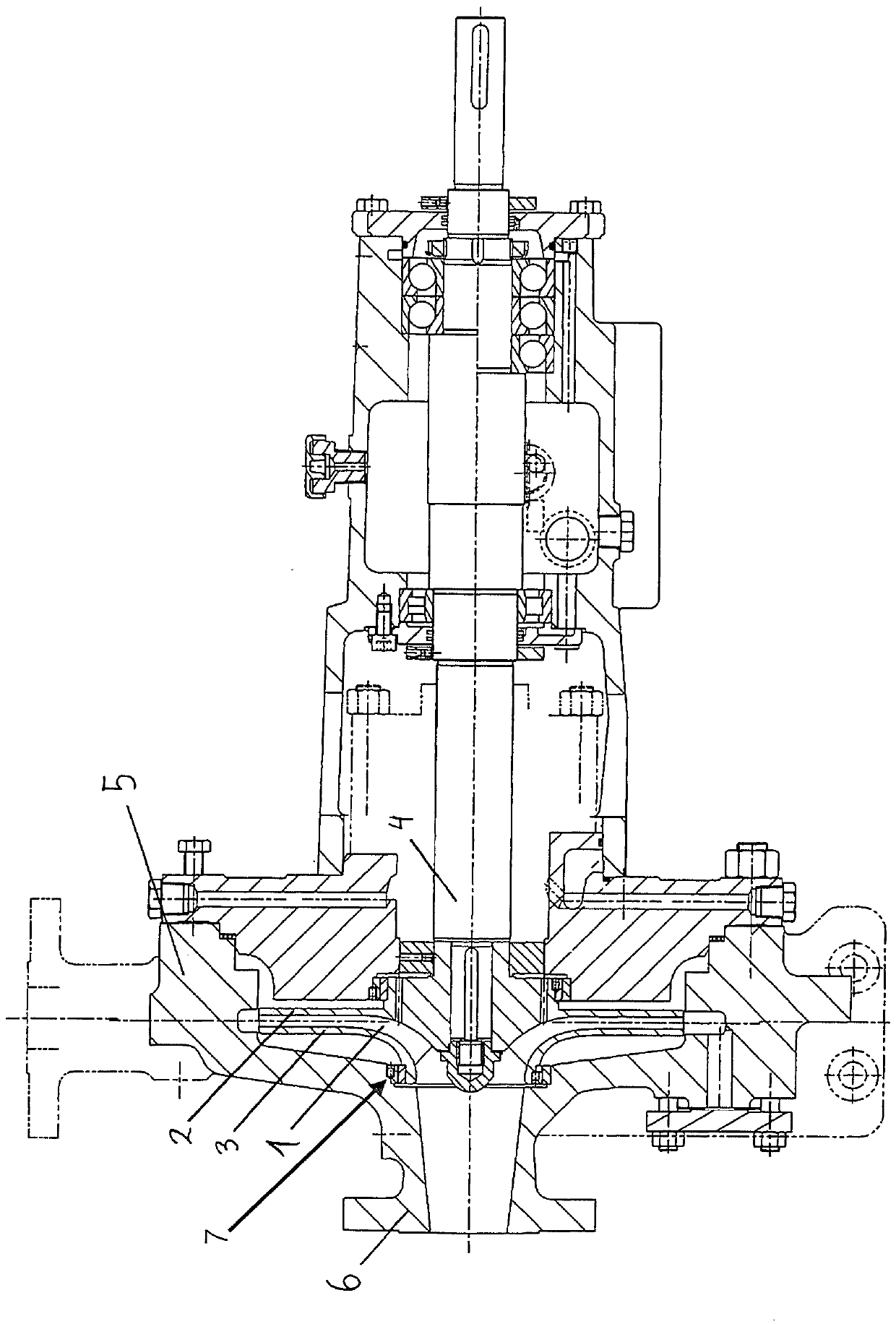
[0029] figure 1 A centrifugal pump with impeller 1 is shown. The impeller 1 is designed as a closed radial impeller and has a carrier disk 2 and a cover disk 3 . Blades are arranged on the carrier plate 2 . A channel for transporting the medium is formed between the carrier tray 2 and the cover tray 3 . The impeller 1 is driven by the shaft 4 . The impeller 1 is surrounded by a housing 5 which can be constructed in multiple parts. The housing 5 has a suction nozzle 6 . The centrifugal pump has a gap ring seal 7 . The gap ring seal 7 limits the gap volume flow, which flows back from the pressure region of the centrifugal pump into the suction region. The impeller 1 is designed as a radial impeller. The fluid flows to the impeller 1 in the axial direction and is then deflected by 90º and discharged from the impeller 1 in the radial direction.

[0030] figure 2 A schematic view of the front wheel-side space 8 formed between the cover plate 3 and the housing part 9 of th...


PUM


Abstract

The invention relates to a centrifugal pump having a radial impeller (1) which is surrounded by a housing (5). The housing (5) has a channel (11). A flow from a wheel side space (8) is led through thechannel (11) to a radial gap (12).

Description

technical field [0001] The invention relates to a centrifugal pump with radial impellers which are surrounded by a housing. Background technique [0002] In radial centrifugal pumps, depending on the type of design, there are resulting axial forces acting on the rotor, which must be compensated. The main component of this axial force is the pressing forces acting on the cover disk or carrier disk, which are directed opposite to each other. Usually, the force acting on the carrier disk is significantly greater than the component acting on the cover disk, so that an axial thrust directed towards the suction side occurs which must be compensated accordingly. Generally, axial thrust is understood as all generated axial forces acting on the mover. [0003] A method and a device for reducing or eliminating axial forces of a centrifugal pump are described in WO 00 / 66894 A1. In a variant, the flow division is realized in that a set of brake vanes is arranged along the circumferen...

Claims


Application Information

Patent Timeline
Patent Type & Authority Applications(China)
IPC IPC(8): F04D29/041F04D29/42
CPCF04D29/0416F04D29/426F04D29/167
Inventor B.威尔
Owner KSB AG
Why Eureka
Try Eureka