Tool receptacle, in particular a quick-change clamping chuck and its protecting device

A protective device and replaceable technology, which is applied in the direction of chucks, portable motorized devices, maintenance and safety accessories, etc., can solve the problem of damaged parts, etc., and achieve the effect of easy installation or disassembly, simple and economical installation or disassembly

Inactive Publication Date: 2005-02-23
ROBERT BOSCH GMBH
0 Cites 2 Cited by

AI-Extracted Technical Summary

Problems solved by technology

When using the portable power tool as intended, there is also the risk that parts in contac...

Method used

[0020] The protector 40 will advantageously be made of a soft, shock absorbing material such as rubber, elastomer, plastic or the like. The protective device 40 has a wall part 41 which is in particular cylindrical and extends axially at least substantially over the entire length of the locking sleeve 24 . A wall part 41 surrounds the locking device over the entire length of the locking sleeve 24 and is held on the locking sleeve in a detachable but non-displaceable...

Abstract

A tool receptacle, in particular a quick-change clamping chuck, particularly for motor-operated hand-held machine tools 10, in particular screwdrivers, drills or the like, has a holding sleeve 21 with a locking arrangement 22 for detachably locking a tool which can be received in said holding sleeve 21. The holding sleeve 21 with the locking arrangement 22 is encompassed, on the outside, by an external protective arrangement 40 which masks their outer faces in a protective manner and which offers protection for the said outer faces as well as for components that come into contact therewith. The tool receptacle 20 is thereby protected against damage, any components that come into contact therewith also being likewise protected against being damaged by said tool receptacle 20.

Application Domain

Portable power-driven toolsChucks +1

Technology Topic

EngineeringMachine tool +2

Image

  • Tool receptacle, in particular a quick-change clamping chuck and its protecting device

Examples

  • Experimental program(1)

Example Embodiment

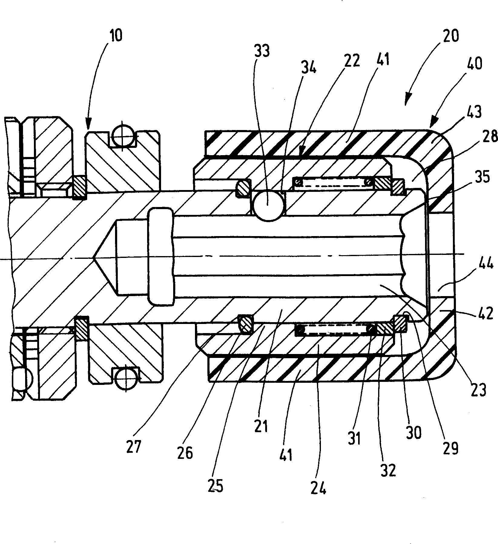
[0015] In the drawing, the end of a portable power-driven machine tool 10 is schematically shown, which is composed of a screwdriver, a drill or similar machine tool and with the aid of an unshown, especially electric The drive motor and a rear-mounted transmission, also not shown, to drive. The portable power tool 10 has at its end an axially arranged tool holder 20 as shown, in particular in the form of a quick-change chuck. The tool holder 20 has a holding sleeve 21 with a locking device 22 for releasably locking a tool not shown that can be received in the holding sleeve 21. The tool will be received by its shaft in an axially inner receiving cavity 23 of the holding sleeve 21, the receiving cavity having, for example, a polygonal profile, such as a hexagonal profile, to fit the corresponding cross-sectional shape of the tool shaft. The locking device 22 has a locking sleeve 24 which overlaps the holding sleeve 21 and can be moved and fixed axially on the holding sleeve. In the figure, an O-ring 26 on the left side of a radially inward annular projection 25 is used for this fixation. The sealing ring is received in the annular groove 27 of the retaining sleeve 21 and serves as the annular projection 25 The stop on the left in the picture.
[0016] In the area of ​​the front end 28 of the holding sleeve 21, a collar 30 is received in an annular groove 29 here, which is used to axially support a spring 31, which uses its left end shaft in the figure The spring is supported on the side facing the annular projection 25 and the spring is used at the opposite end to rest on the supporting ring 32 on the retaining sleeve 21, which is supported on the collar 30 . The spring 31 functions as a compression spring, and its spring preload is guaranteed by the support ring 32 and the clamp ring 30. The locking sleeve 24 is continuously held in the locked position shown by the spring 31, and a tool inserted in the receiving cavity 23, such as a shaft of a screwdriver, is axially locked in the locked position in. At least one locking element 33 in the form of a radially movable ball is used for this locking, and the locking element is held in an additional radial hole 34 of the retaining sleeve 21 in such a way that it cannot fall off, that is, for unlocking through the lock The movement of the stop sleeve 24 to the right in the figure causes the at least one locking member 33 radially released by the annular protrusion 25 to move radially outward in the radial hole 34 and release the tool. In the position shown in the figure, the locking member 33 is pressed radially toward the center of rotation of the tool holder 20 by the annular projection 25 with an unshown tool inserted in the receiving cavity 23 locked. direction.
[0017] The clamp ring 30 located in the area of ​​the front end 28 ensures the functional capability of the tool holder 20 in the form of a quick-change chuck. Due to the position of the collar 30, the collar lacks resistance to mechanical loads, especially damage. If damage occurs in this area, the collar 30 will be damaged, thereby causing the tool holder 20 to lose all its functional capabilities.
[0018] The outer surface of the locking sleeve 24 and the outer surface of the free front end of the holding sleeve 21 and the collar 30 may damage the parts in contact with them. This risk of damage exists in the area of ​​these components connected to each other, for example, by means of a portable power tool 10 in the form of a screwdriver. This may be a body part that is built and painted in vehicle manufacturing, and these parts are to be connected to each other or connected to the part to be fixed by screws (bolts).
[0019] In order to remedy this and to protect the tool holder 20 from damage on the one hand, and on the other hand to protect the parts connected by the portable machine tool 10 from damage to the tool holder 20, the following is designed: 22 is surrounded on the outside by an external protection device 40 that protectively covers their outer surfaces, which protects on the one hand these external surfaces and on the other hand protects the parts that come into contact with them, such as the parts to be connected. The protection device 40 ensures the protection against damage to the mechanical parts of the tool holder 20 and the parts connected to the portable machine tool 10 to be used. The protection device is easy to install and disassemble. It can be installed on the portable machine tool 10 already in operation in a simple manner afterwards. If the protection device 40 is damaged, damaged or completely worn out, the original function of the tool holder 20 is still fully guaranteed. The protection device 40 can be installed on the tool holder 20 by hand without any auxiliary device in a simple manner. The operation of the portable power tool 10 will not be changed due to the installation of the protection device 40.
[0020] The protective device 40 will advantageously be made of a soft, vibration-damping material such as rubber, elastomer, plastic, etc. The protection device 40 has a wall portion 41 which is in particular cylindrical and extends at least substantially over the entire length of the locking sleeve 24 in the axial direction. The wall portion 41 surrounds the locking device over the entire length of the locking sleeve 24, and the wall portion 41 is detachably but immovably and/or non-rotatably held on the locking sleeve. This can be achieved in a simple manner, that is, the wall portion 41 is sleeved on the locking sleeve 24 and clamped to the locking sleeve. In this case, the holding effect is also supported as follows: the locking sleeve 24 is provided with embossing on its outer surface in the usual manner, which serves as a surface roughness to further improve the gap between the surface and the wall portion 41 of the protection device 40 Traction.
[0021] The protection device 40 extends beyond the free front end 28 of the holding sleeve 21. Here, it is sufficient that the particularly cylindrical wall portion 41 is axially extended by a corresponding flange (Bund), and the entire protective device 40 is formed only by the axial direction between the cylindrical wall portion and the front end 28. The extension part is composed, wherein the axial extension part extends over the front end face 35 of the holding sleeve 21, and in this way, not only the tool holder 20 but also the parts connected by the portable power tool 10 can be ensured corresponding contact protection.
[0022] In the illustrated embodiment, the protection device 40 is configured as follows: it protects the front end surface 35 of the holding sleeve 21 and a ring portion 42 rests on the end surface 35 and covers the end surface. In this case, the ring portion 42 is connected to the end side of the wall portion 41, and the ring portion 42 is preferably integral with the wall portion. In this configuration, the protective device 40 is composed of a substantially pot-shaped protective cover 43, whose wall is composed of a wall portion 41 and its bottom is composed of a ring portion 42, wherein the ring portion 42 includes a through hole 44 in the center, The through hole can be penetrated by an inserted tool.
[0023] The protective cover 43 is pushed onto the locking sleeve 24 from the free front end 28 of the holding sleeve 21 and clamped on it, and covers the locking sleeve 24 and the free front end of the holding sleeve 21 from the outside. 28, and cover the components provided on it, such as the support ring 32 and the collar 30.
[0024] It can be understood that the protection device 40 can be simply used as an independent component and no auxiliary device is necessary. It can be installed on the tool holder 20 afterwards at any time, and thus can be advantageously used as a retrofit to an existing portable machine tool. 10 parts.

PUM

no PUM

Description & Claims & Application Information

We can also present the details of the Description, Claims and Application information to help users get a comprehensive understanding of the technical details of the patent, such as background art, summary of invention, brief description of drawings, description of embodiments, and other original content. On the other hand, users can also determine the specific scope of protection of the technology through the list of claims; as well as understand the changes in the life cycle of the technology with the presentation of the patent timeline. Login to view more.

Similar technology patents

Metal die tool

InactiveCN106424566AEasy to install and removeImprove casting efficiency
Owner:TIANJIN LONGHE STEEL ALTERED METAL PROD CO LTD

Drawer backboard connecting device

InactiveCN101606787AEasy to install and removeEliminate shear force
Owner:李绍汉

Mail reminder

InactiveCN103713985AThe screws are fixed firmlyEasy to install and remove
Owner:谢虹

Classification and recommendation of technical efficacy words

Why Eureka
Try Eureka