

Grounded resistance measuring apparatus
A measuring device and a technology of grounding resistance, which are applied in the field of grounding resistance measuring devices, can solve problems such as measurement errors, different readings, cumbersome operations, etc., achieve accurate measurement results, avoid measurement errors, and have simple measurement methods
- Summary
- Abstract
- Description
- Claims
- Application Information
AI Technical Summary
Problems solved by technology
Method used
Image

Examples
Embodiment Construction
[0046] Best practice:
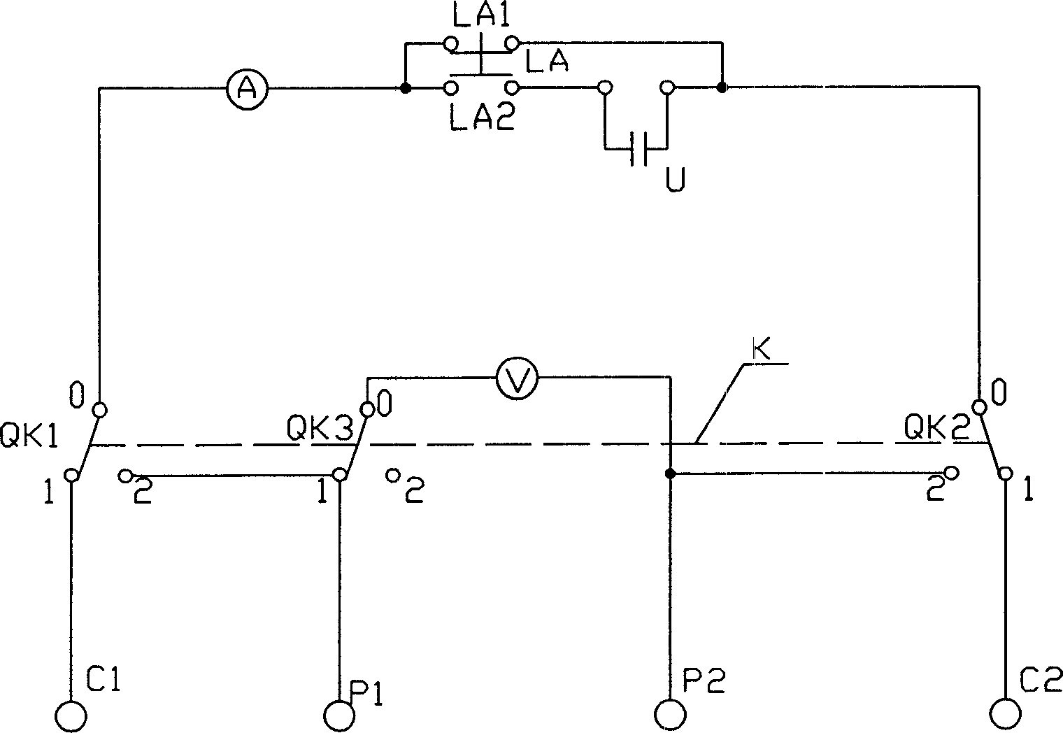
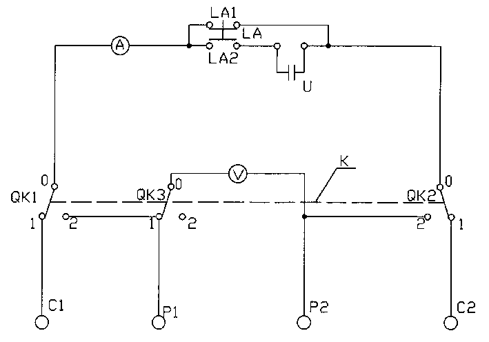
[0047] see figure 2 , a grounding resistance measurement device, including a current measurement loop and a voltage measurement loop, wherein:
[0048] 1) The current measurement circuit includes a power supply U, an ammeter A, a first switch LA1, a second switch LA2, a third switch QK1 and a fourth switch QK2, a first current ground terminal C1 and a second current ground terminal C2;
[0049] The ammeter A is a digital ammeter;
[0050] The power supply U is a supercapacitor power supply;
[0051] The first switch LA1 is connected in series with the supercapacitor power supply U to form a power supply circuit;
[0052] The digital ammeter A is connected in series with the power supply circuit to form a meter circuit;
[0053] ●The first current ground terminal C1, the third switch QK1, the meter circuit, the fourth switch QK2 and the second current ground terminal C2 are electrically connected in series in sequence,
[0054] ●The second switch L...
PUM
 Abstract
Description
Claims
Application Information