
Connecting wire arranging method in disc device

A technology of an optical disc device and a configuration method, which is applied in the directions of optical recording/reproducing, data recording, instruments, etc., can solve the problems of increasing the production cost of thin optical disc devices and the like

Inactive Publication Date: 2005-02-23
LITE ON TECH CORP
View PDF0 Cites 0 Cited by
  • Summary
  • Abstract
  • Description
  • Claims
  • Application Information

AI Technical Summary

Problems solved by technology

If you need to use non-standard flexible cables, you must redesign the flexible cables with a specific number of connecting lines and order them from the manufacturer, which will increase the production cost of the thin optical disc device

Method used


Image

  • Connecting wire arranging method in disc device
  • Connecting wire arranging method in disc device
  • Connecting wire arranging method in disc device

Examples


Embodiment Construction

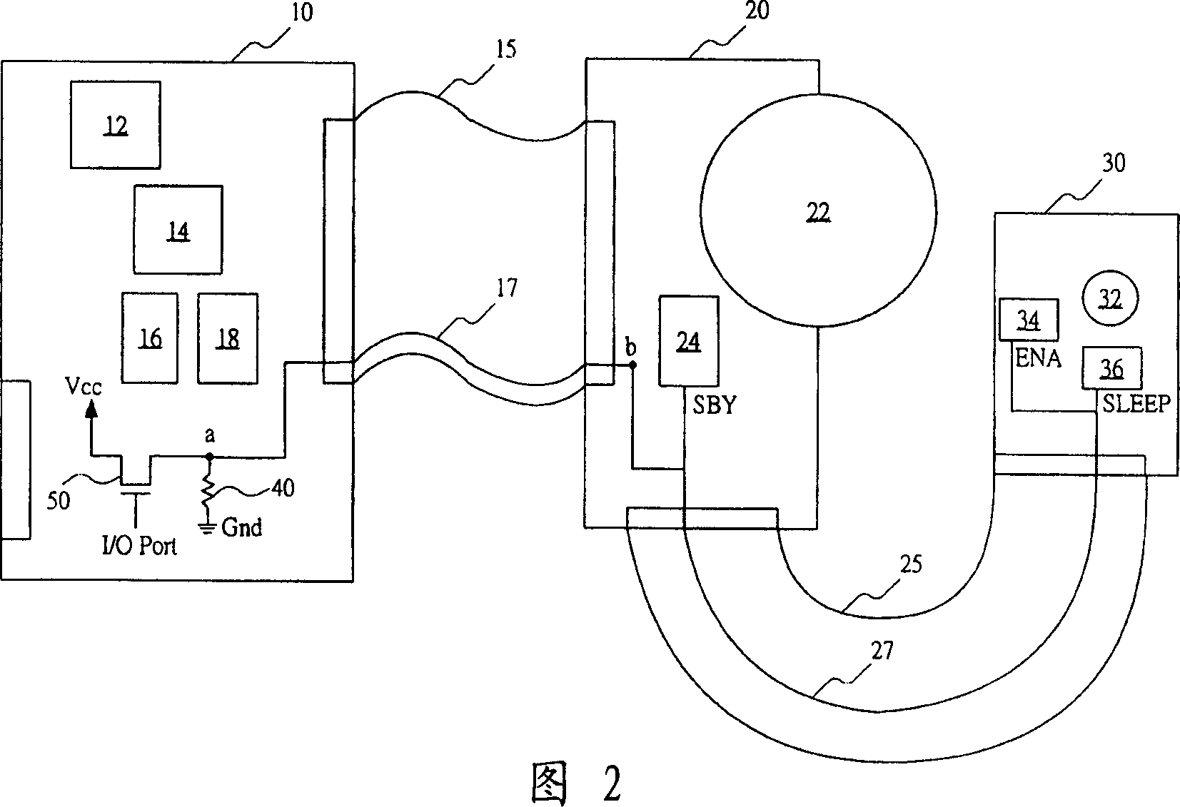
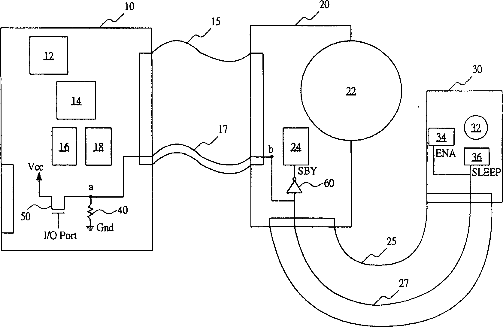
[0025] In order not to increase the number of flexible cables, the functions of all the pins of the spindle motor driver chip 24 on the sub-circuit board 20 and the laser diode driver chip 34 and the photodetector chip 36 on the optical read-write head 30 must be repeated. confirm. That is to say, the present invention provides only one connection line for signals with similar functions to connect the main circuit board 10 and the sub-circuit board 20 .

[0026] Please refer to FIG. 2 , which is a schematic view showing the arrangement of connecting wires in the thin optical disc device of the present invention. First, a switch circuit 50, such as a FET transistor, is provided between the power supply voltage (Vcc) and the first node "a" on the main circuit board 10, and an I / O port (I / O Port) is used to control the switching circuit. Open (Off) and connected (On). Moreover, a pull-down resistor (Pull-Down Resister) 40 is coupled between the first node "a" and the ground vol...


PUM


Abstract

In this invention the configuration method of the connection of the CD apparatus is illustrated. The invention is to ensure all the control chips on the circuit board and the optical read-write head possesses the pins with same function, and supplies the bendable connecting lire to connect with pins of same function, thus achieves the saving to the number of the connecting lines.

Description

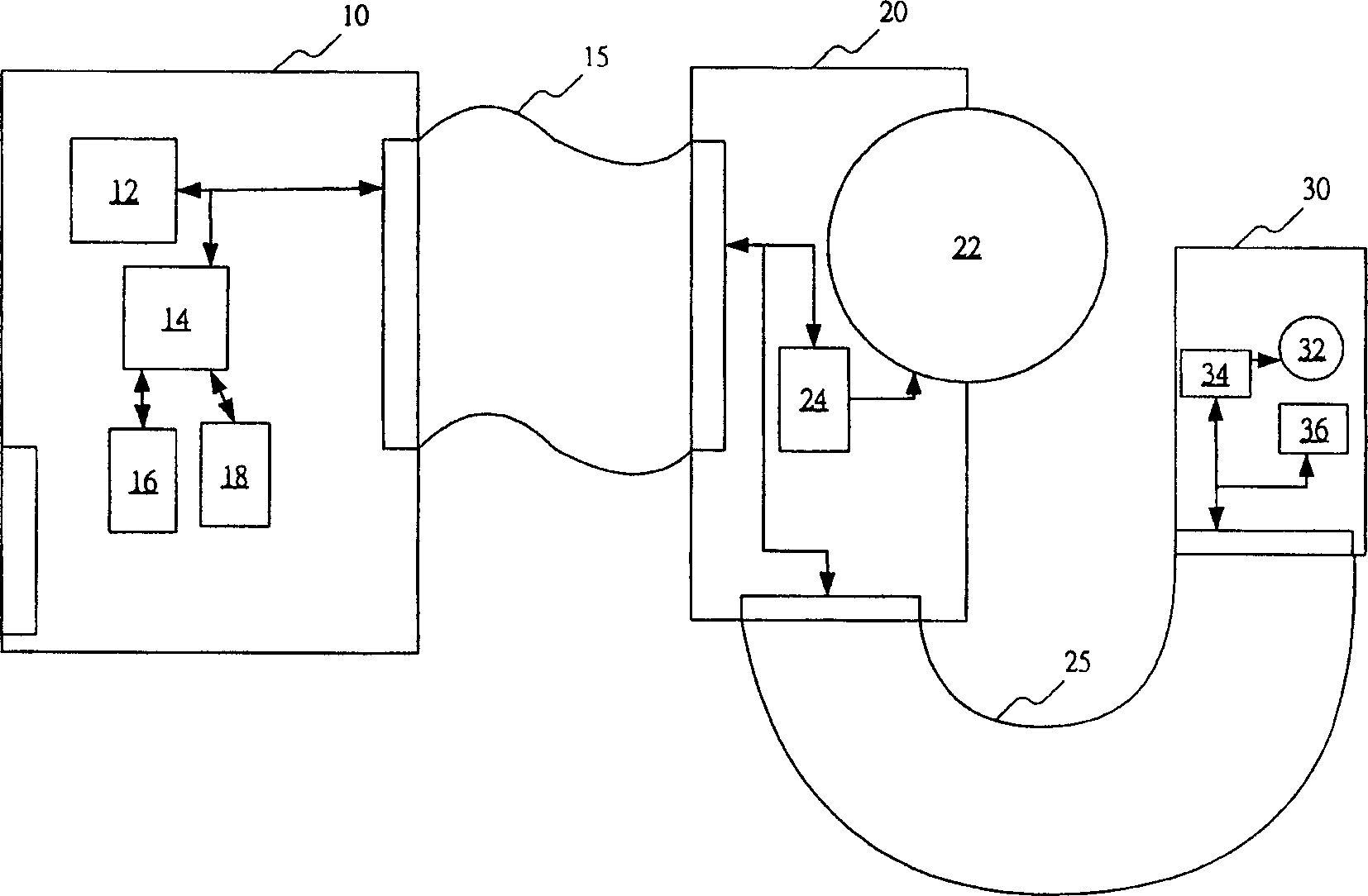
technical field [0001] The present invention relates to the arrangement of connecting wires of the control chip in the optical disc device, and in particular to the method for configuring the connecting wires of the control chip in the thin optical disc device. Background technique [0002] Please refer to figure 1 , which is a schematic diagram showing the layout of the thin optical disc device. Generally speaking, the circuit board of the thin disc device can be divided into two parts, the sub-board (Sub-Board) 20 is fixed on the movable tray (Tray), and the main circuit board (Main Board) 10 is fixed on the casing. [0003] Furthermore, an analog signal processor (Analog Signal Microprocessor) 12, a digital signal processing / decoding processor (DSP / Decoder Microprocessor) 14, a flash memory chip (Flash ROM) 16, a static random access memory (SDRAM) are arranged on the main circuit board 10. ) chip 18. The first flexible cable (Flexible Cable) 15 connected between the t...

Claims


Application Information

Patent Timeline
IPC IPC(8): G11B7/00G11B33/00
Inventor 徐正煜庞家元蔡松峰蔡燿州
Owner LITE ON TECH CORP
Learn More