
Method for regulating the power supply of a number of field devices

A field device, stable technology, applied in the field of stabilizing the power supply of multiple field devices, can solve the problems of expensive, low consumption value of independent field devices, low measurement rate of independent field devices, etc.

Inactive Publication Date: 2005-02-23
EHNDRESS KHAUZER GMBKH KO KG
View PDF0 Cites 6 Cited by
  • Summary
  • Abstract
  • Description
  • Claims
  • Application Information

AI Technical Summary

Problems solved by technology

If as many field devices as possible are connected to the fieldbus, the consumption values ​​of the individual field devices must be kept as low as possible, and this means that the result is a low measurement rate for the individual field devices
[0012] If the consumption value of an individual field device has to be reduced because another field device is to be connected to the fieldbus, this can be done manually, which is expensive

Method used


Image

  • Method for regulating the power supply of a number of field devices
  • Method for regulating the power supply of a number of field devices
  • Method for regulating the power supply of a number of field devices

Examples


Embodiment Construction

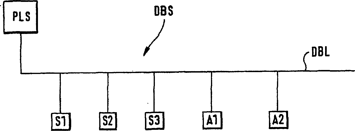
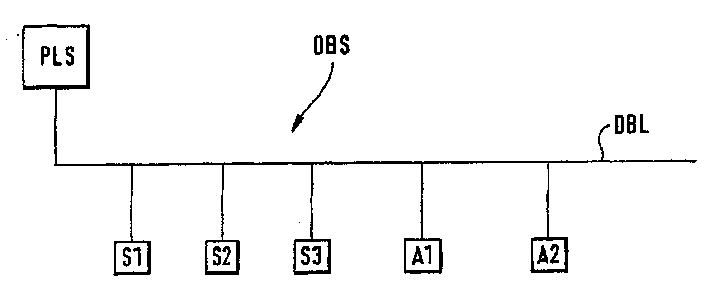
[0022] figure 1 A data bus system DBS comprising a plurality of field devices and a process control system PLS is shown. Field devices include sensors S and actuators A. The data bus participants are connected to the field bus DBL. The process control system PLS is usually placed in a control room from which the entire process control takes place centrally. Sensor S and actuator A are placed "in situ" at separate process elements (tanks, feeding equipment, pipelines, etc.). Sensors S1 , S2 and S3 detect eg process variables temperature T, pressure P and flow F at a specific process element in each case. Actuators A1 and A2 are, for example, valve controllers that stabilize the flow of liquid or gas through a length of pipeline. Data transfer between process control system PLS, sensor S and actuator A in a known manner using special protocols (e.g. PROFIBUS or FOUNDATIONFIELDBUS, CAN-Bus) according to international standard transmission technologies (e.g. RS 485 or IEC1158)...


PUM


Abstract

In a method for stabilizing the power supply of a plurality of field devices S1, S2, S3, A1, A2, the current demand of the individual field devices S1, S2, S3, A1, A2 is determined and the field Current consumption of the devices S1 , S2 , S3 , A1 , A2 , wherein a plurality of field devices S1 , S2 , S3 , A1 , A2 are connected to the data bus DBL and supplied with current via the data bus DBL. In this way, the current consumption of the individual field devices S1 , S2 , S3 , A1 , A2 can be regulated centrally and thus adapted to the process conditions.

Description

technical field [0001] The invention relates to a method for stabilizing the power supply of a plurality of field devices. Background technique [0002] In automation and process control technology, field devices are frequently used to detect process variables (sensors) and control control variables (actuators). [0003] Field devices are known for determining flow rates, filling levels, differential pressures, temperatures, etc. In order to detect the corresponding process variables, such as mass or volume flow rate, filling height, pressure, temperature, etc., field devices are placed in the immediate vicinity of the relevant process elements. [0004] The field device sends a measurement signal representing a measured value of the sampled process variable. This measurement signal is sent to a central control unit (eg a control room or a process control system). Usually, the entire process control starts with a control unit, where the measurement signals of the differen...

Claims


Application Information

Patent Timeline
Patent Type & Authority Applications(China)
IPC IPC(8): H02J13/00G05F1/00G05F1/10H04L12/10
CPCY10T307/438Y10T307/865H04L12/10Y10T307/43
Inventor 斯特凡·迈尔
Owner EHNDRESS KHAUZER GMBKH KO KG
Learn More