After-planting expansion piece

A technology of expansion and post-planting, which is applied in the direction of building components, building reinforcements, structural elements, etc., and can solve problems such as loosening, fitting, and pull-off

Inactive Publication Date: 2005-03-02
徐洁媛
View PDF0 Cites 2 Cited by
  • Summary
  • Abstract
  • Description
  • Claims
  • Application Information

AI Technical Summary

Problems solved by technology

[0002] Install and fix some building installation parts on the surface of the building parts. At present, the pre-planting method is commonly used, that is, the planting bars are embedded and poured together with the building parts when pouring the building parts. With this structural method, the position of the pre-planting parts is very small. It is difficult to accurately match the design position, and once the installation position of the installation part is changed or new installation parts are added, especially when the building installation parts are installed on the existing building parts, the pre-planting parts are helpless. Therefore, this structure is in It is very inconvenient in actual use and has great limitations
There is also a method to process deep smooth straight holes on the surface of building parts and embed planting bars. However, the bonding strength between planting bars and hole walls is limited at present. Under the influence, it is easy to loosen with the building parts. Once it is subjected to strong external forces such as earthquake force or strong typhoon, there is a danger of being pulled off

Method used


Image

  • After-planting expansion piece
  • After-planting expansion piece
  • After-planting expansion piece

Examples


Embodiment 1

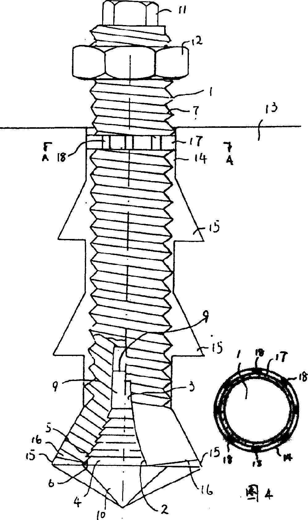
[0018] Refer to attached figure 1 . The present invention comprises expansion rod 1, and the lower end of expansion rod is provided with expansion mechanism, and expansion mechanism comprises expansion hole 2 at the lower end of expansion rod, and the expansion part of expansion hole is provided with expansion slot 3, and it is also provided with the upper end that cooperates with expansion hole. Conical head 4 with guide section 9 .

[0019] The surface of the expansion hole wall is provided with anti-slip lines 5, and the conical surface of the conical plug is provided with anti-slip lines 6 matching the aforementioned anti-slip lines. The anti-slip lines on the surface of the hole wall are anti-slip teeth, and correspondingly, the anti-slip lines on the conical surface of the plug are matched anti-slip teeth.

[0020] Refer to attached figure 1 , 4 The upper part of the expansion rod is covered with a ring 17, and several protrusions 18 are distributed on the surface of ...

Embodiment 2

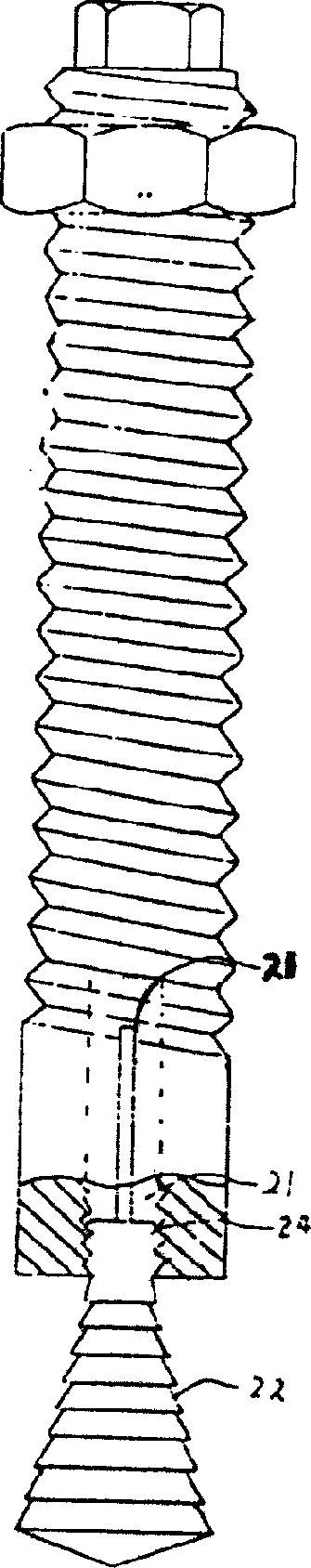
[0027] Refer to attached figure 2 . In this embodiment, the guide section 22 of the plug is threadedly matched with the expansion hole 21, and the reference number 23 is the expansion hole. Others are with embodiment 1.

Embodiment 3

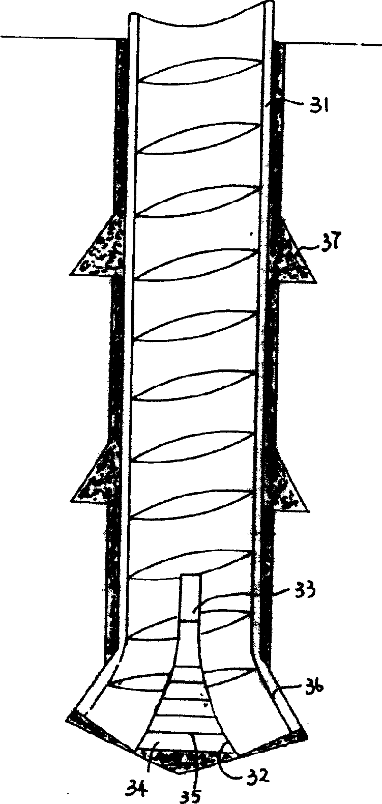
[0029] Refer to attached image 3 . The expansion rod 31 of the present embodiment is a threaded steel bar, and the lower end of the expansion rod is provided with an expansion hole 32, and the expansion part of the expansion hole is provided with an expansion slot 33, and it is also provided with a tapered top 34 cooperating with the expansion hole.

[0030] The surface of the expansion hole wall is provided with anti-slip lines, and the conical surface of the conical plug is provided with anti-slip lines 35 matching the aforementioned anti-slip lines. The anti-slip lines on the surface of the hole wall are anti-slip teeth, and correspondingly, the anti-slip lines on the conical surface of the plug are matched anti-slip teeth.

[0031] Reference number 36 is the expansion part of the expansion rod. Reference numeral 37 is cement slurry or construction adhesive etc.


PUM


Abstract

The post-mounted expansion unit includes an expansion rod, and an expansion mechanism in the lower part of the expansion rod, and the expansion mechanism includes the expansion hole in the lower part of the expansion rod, expansion slot and conic push head with guide section and matching the expansion hole. The said technological scheme has strong and firm expansion rod, and expansion mechanism with obviously raised connection strength between the post-mounted part and the deep hole. In addition, the expansion hole wall and the conic push head have anti-skid thread to further raise the connected strength.

Description

technical field [0001] The invention relates to a post-plant expansion part applied to building parts. Background technique [0002] Install and fix some building installation parts on the surface of the building parts. At present, the pre-planting method is commonly used, that is, the planting bars are embedded and poured together with the building parts when pouring the building parts. With this structural method, the position of the pre-planting parts is very small. It is difficult to accurately match the design position, and once the installation position of the installation part is changed or new installation parts are added, especially when the building installation parts are installed on the existing building parts, the pre-planting parts are helpless. Therefore, this structure is in Very inconvenient during actual use, limitation is very big. There is also a method to process deep smooth straight holes on the surface of building parts and em...

Claims


Application Information

Patent Timeline
Patent Type & Authority Applications(China)
IPC IPC(8): E04C5/12
Inventor 徐洁媛徐跃华
Owner 徐洁媛
Why Eureka
Try Eureka