Glass cone for projection tube

A technology for projection and tube application in the direction of cathode ray/electron beam tube shell/container, which can solve problems such as scratches, small cracks, and wrinkles

Inactive Publication Date: 2005-03-02
HENAN ANCAI HI-TECH
View PDF1 Cites 0 Cited by
  • Summary
  • Abstract
  • Description
  • Claims
  • Application Information

AI Technical Summary

Problems solved by technology

Due to the molding method and characteristics of the funnel-shaped funnel for the projection tube, it can be known that if the radius of curvature of the connecting curved surface between the side wall surface of the fixed seat and the outer wall surface of the side wall of the funnel-shaped funnel is too small, the side wall of the fixed seat will The demoulding angle is also small, so when the funnel-shaped funnel is pressed and formed, it is difficult for the molten glass gobs to evenly and fully fill the cavity corresponding to the fixed seat of the mold, which will inevitably cause defects such as insufficient filling or wrinkles
In addition, it will be difficult to pull out the funnel-shaped funnel from the mold, and defects such as scratches or small cracks will occur on the side wall...

Method used


Image

  • Glass cone for projection tube
  • Glass cone for projection tube
  • Glass cone for projection tube

Examples


Embodiment Construction

[0016] The present invention will be described in detail below with reference to the accompanying drawings.

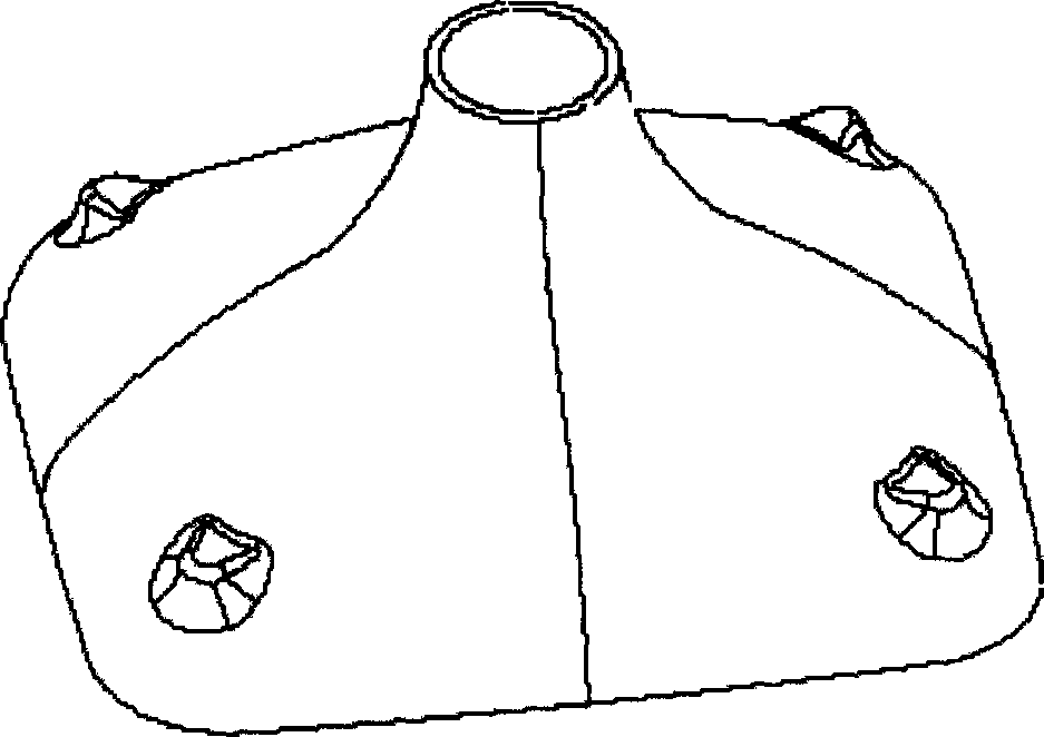
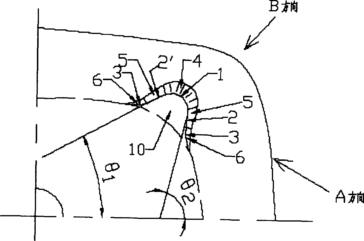
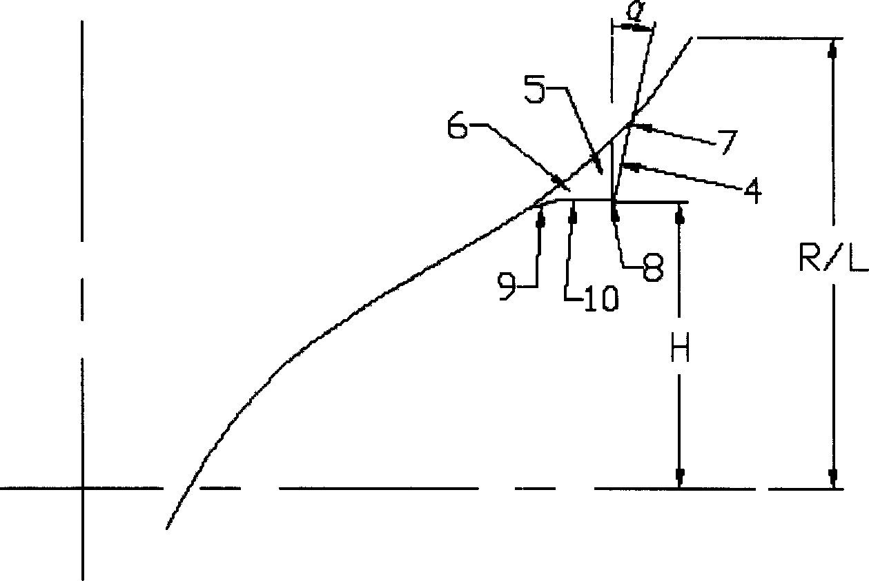
[0017] figure 1 A perspective view of a funnel for a projection tube. figure 2 It is a schematic diagram of the funnel fixing seat for the projection tube along the direction of the center axis of the funnel for the projection tube. see figure 1 and figure 2 , which has a plurality of fixing seats for fixing a cooling device, and each fixing seat is integrally protruded from a funnel-shaped projection tube with a substantially rectangular large opening at one end and a small circular opening at the other end. On the outer wall surface of the side wall portion, the end face of the fixed seat close to the circular small opening end of the funnel-shaped projection tube funnel is the reference end face 10, and the protruding ridge line of the reference end face 10 is defined by the first curve Part 1, second curved part 3 and straight part 2, 2', wherein the first ...


PUM


Abstract

The fixing base of glass cone of projection tube used for fixing cooler which is fit on outside surface of side wall of glass cone used for reference end surface of fixing base includes first curve section, second curve section and straight-line section, the first and second curve section are smoothly connected by the straight-line section, the straight-line section is smooth connected on outside wall surface of side wall of funnel-shaped glass cone through the second curve section. The side wall section is formed by stretching bulged crest line forming reference end surface along center axial direction of the funnel-shaped glass cone in an angle, both reference end surface and side wall section of the fixing base are smooth connected with the outside surface of projection tube used glass cone.

Description

technical field [0001] The invention relates to a funnel-shaped funnel for a projection tube. The fixing seat used for fixing the cooling device is integrally protrudingly arranged on the outer wall surface of the side wall of the funnel for a funnel-shaped projection tube. Background technique [0002] As a cathode ray tube constituting a main part of a display device such as a television, there are generally a direct view type cathode ray tube and a projection cathode ray tube. The components of both cathode ray tubes include a funnel-shaped funnel for mounting an electron gun. [0003] Compared with direct-view cathode ray tubes that display images by arranging RGB ternary color lights on the display screen, projection cathode ray tubes use three cathode ray tubes to irradiate RGB color lights respectively, and then respectively irradiate the RGB colors. The color light is expanded and projected onto the fluorescent screen to display the image. In such projection cathod...

Claims


Application Information

Patent Timeline
IPC IPC(8): H01J29/86
Inventor 贾伟邵玉杰任清海朱占峰李葆如王玮
Owner HENAN ANCAI HI-TECH
Why Eureka
Try Eureka