Jet nozzle for textile machine and its cleaning method

A processing machine and nozzle technology, applied in the direction of spraying/jetting textile material treatment, spraying devices, etc., can solve problems such as nozzle clogging, achieve the effects of no clogging and reduced dyeing liquid volume

Inactive Publication Date: 2005-03-09
FALMER INVESTMENTS LTD
View PDF0 Cites 1 Cited by
  • Summary
  • Abstract
  • Description
  • Claims
  • Application Information

AI Technical Summary

Problems solved by technology

Therefore, despite having a larger inlet and outlet, and a larger nozzle chamber, the nozzle will still clog

Method used


Image

  • Jet nozzle for textile machine and its cleaning method
  • Jet nozzle for textile machine and its cleaning method
  • Jet nozzle for textile machine and its cleaning method

Examples


Embodiment Construction

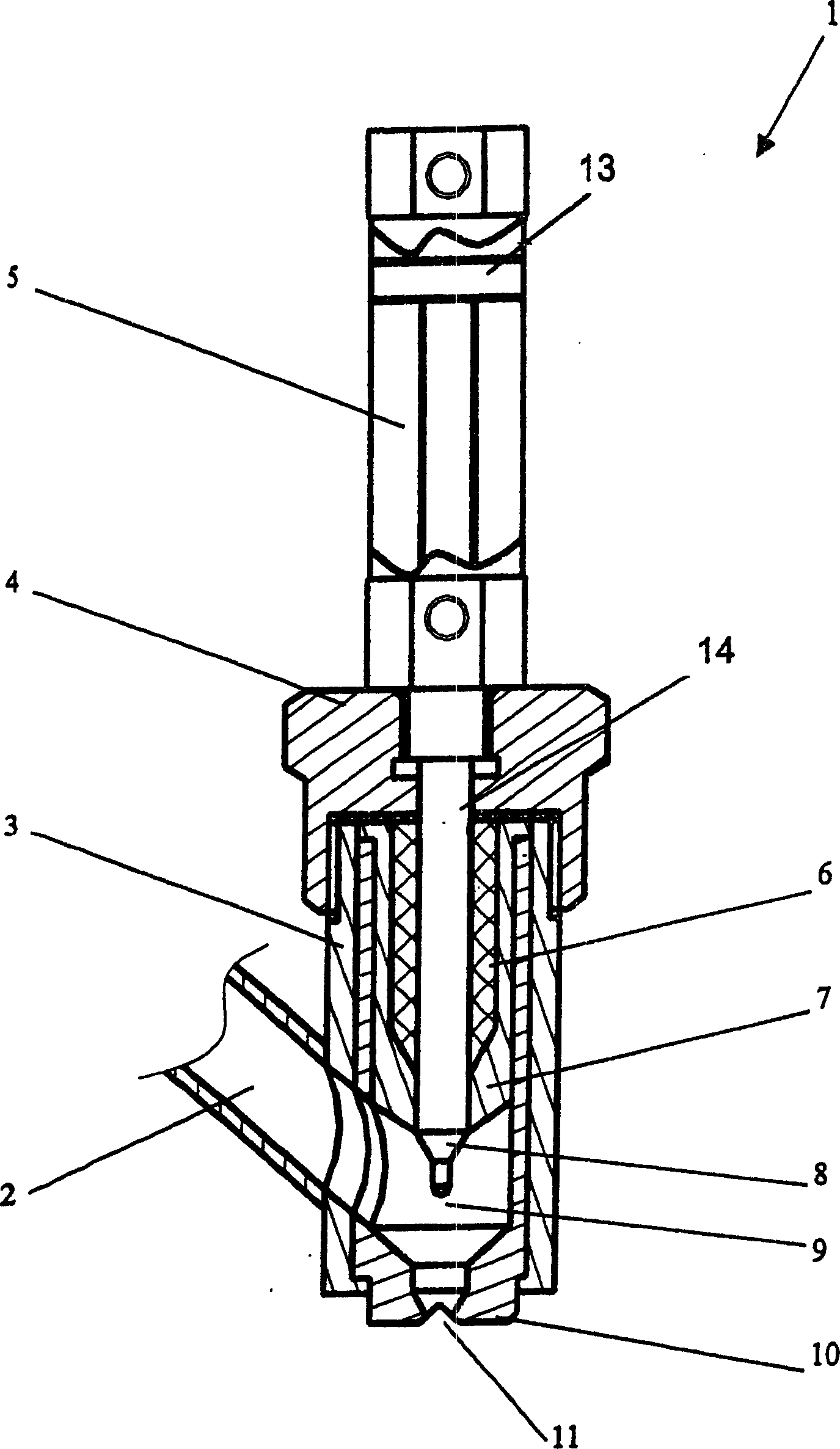
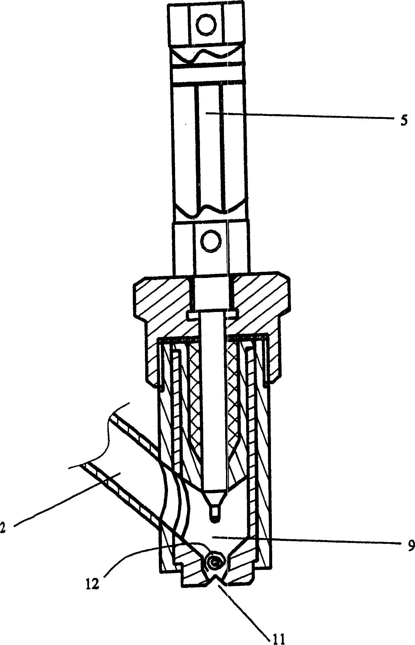
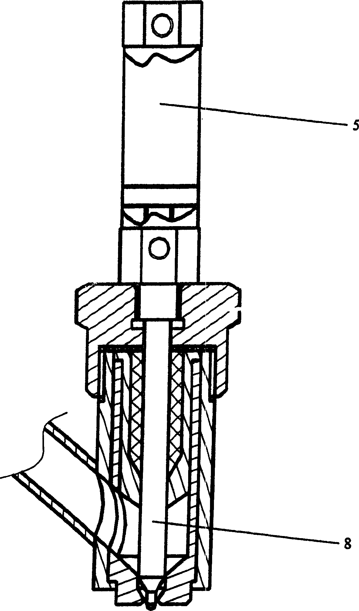
[0046] The present invention will be described in further detail below in conjunction with the accompanying drawings: figure 1 Shown are the components available for a self-cleaning nozzle assembly 1 for use with a textile processing machine (not shown).

[0047] The self-cleaning nozzle assembly 1 includes a nozzle housing 3 and a nozzle body 10 wrapped in the nozzle housing 3 . The nozzle housing 3 and the nozzle body 10 have corresponding fluid inlets 2 provided on the side walls.

[0048] The nozzle body 10 forms a fluid channel 9 . In this embodiment, this fluid channel 9 has a circular cross-section. At one side end of the fluid channel 9 it is provided with an outlet 11 . The outlet 11 has a generally oval or eye-shaped configuration.

[0049] The range of the fluid channel 9 is jointly defined by the inlet 2, the outlet 11 and the base of the sealing support 7 provided on the side wall. The seal support 7 may provide a substantially liquid-tight seal at the end of...


PUM


Abstract

The invention provides a nozzle (1) for textile processing machine and clean method thereof. The nozzle includes a nozzle body (10) having outlet (11), and clean member (8) movable in the outlet (11). At normal position, the clean member (8) is separated from the outlet (11), and at the clean position, the clean member (8) can move in cooperation with the outlet (11), and assists to remove block article (12) existing in region of the outlet (11).

Description

technical field [0001] The present invention relates to a textile processing machine, in particular to a jet dyeing machine, but not limited thereto. Background technique [0002] Textile processing machines, particularly jet dyeing machines, use fluid jet nozzles to apply processing fluids to and into textiles passing through the processing machine. [0003] On a typical jet dyeing machine, the processing fluid applied to the textile is a dyebath, a solution of dyestuff and water. The dye liquor is applied to the textiles through a series of nozzles. It will be appreciated that the textile may be any weave or cloth, or any fiber or yarn suitable for weaving into a weave or cloth. Examples of textiles that can be passed through a jet dyeing machine are braids, formed by compressing and twisting a width of textile into a rope-like form. [0004] Prior art nozzles for textile processing machines have large nozzle chambers, as well as large nozzle inlets and outlets, in orde...

Claims


Application Information

Patent Timeline
Patent Type & Authority Applications(China)
IPC IPC(8): B05B15/02D06B1/02
Inventor 徐达明
Owner FALMER INVESTMENTS LTD
Why Eureka
Try Eureka