Scroll-type compressor

A scroll compressor and movable scroll technology, which is applied in the direction of rotary piston machinery, rotary piston pump, mechanical equipment, etc., can solve the problems such as the stable revolution of the movable scroll.

Inactive Publication Date: 2005-03-09
DAIKIN IND LTD
View PDF1 Cites 8 Cited by
  • Summary
  • Abstract
  • Description
  • Claims
  • Application Information

AI Technical Summary

Problems solved by technology

In this way, it is impossible for the above-mentioned compressor to make the counter-pressing force correspond to the change of the overturning moment of the movable scroll OS during the revolution process, and it is impossible to make the revolution movement of the movable scroll very stable.

Method used


Image

  • Scroll-type compressor
  • Scroll-type compressor
  • Scroll-type compressor

Examples


no. 1 example

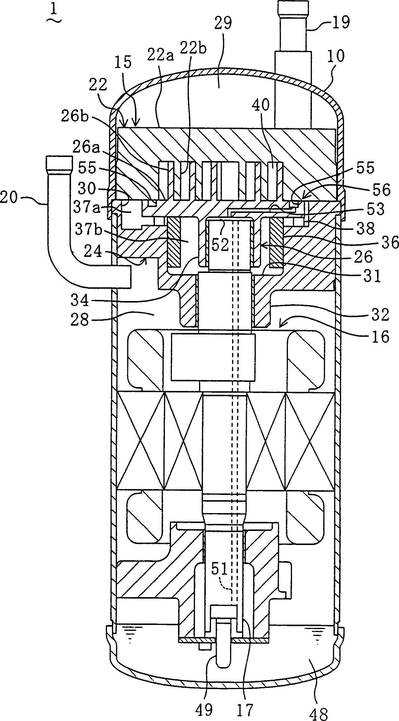
[0061] Next, a first embodiment of the present invention will be described with reference to the drawings. The scroll compressor 1 in the first embodiment is a machine that compresses a refrigerant connected to a refrigerant circuit that performs a refrigerating cycle operation by circulating a refrigerant, which is not shown in the drawing.

[0062] Such as figure 1 As shown, this scroll compressor 1 has a casing 10 constituted by a closed domed pressure vessel. A compression mechanism 15 for compressing refrigerant gas and a compressor motor 16 for driving the compression mechanism 15 are accommodated inside the casing 10 . A compressor motor 16 is arranged below the compression mechanism 15 . Moreover, the compression mechanism 15 and the compressor motor 16 are connected together by a drive shaft 17 .

[0063] The above-mentioned compression mechanism 15 has: a fixed scroll 22 ; a frame 24 arranged so as to be tightly coupled under the fixed scroll 22 ; and a movable s...

no. 2 example

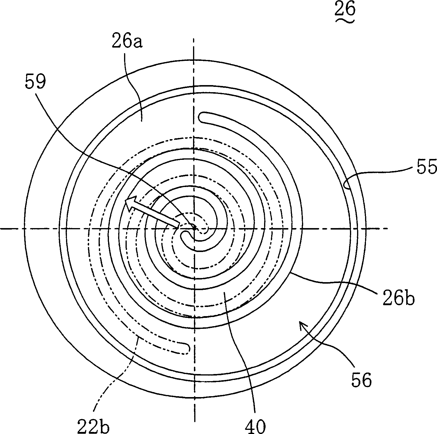
[0078] In the scroll compressor 1 in the second embodiment, only the adjustment mechanism 56 is different from the first embodiment. Specifically, if image 3 As shown, the shape of the oil groove 55 constituting the adjustment mechanism 56 is different from that of the first embodiment. The oil groove 55 is on the movable scroll 26 and has a circular ring shape concentric with the center of the scroll 26 b of the movable scroll 26 , and a part of the oil groove on the side where the overturning moment acts on the center of the movable scroll 26 62 is in an interrupted shape. In this way, the oil groove 55 is C-shaped in plan view.

[0079] In addition, the above-mentioned oil groove 55 is formed in an arc shape with a predetermined constant width. Moreover, in the part 62 of the oil groove 55 where the overturning moment acts, that is, the part where no groove is formed, within the range of the revolution angle in which the overturning moment acting on the movable scroll 2...

no. 3 example

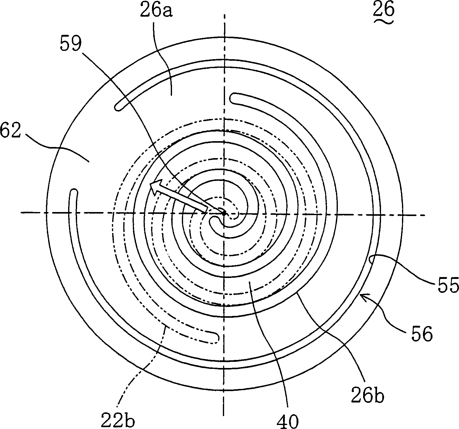
[0086] In the scroll compressor 1 of the third embodiment, the adjustment mechanism 56 is different from those of the first and second embodiments. Specifically, if Figure 4 As shown, the shape of the oil groove 55 constituting the adjustment mechanism 56 is different from those in the first and second embodiments.

[0087] The oil groove 55 is formed concentrically with the center 59 of the movable scroll 26 on the sliding surface of the movable scroll 26 . Such an oil groove 55 is formed in an annular shape, and a width-enlarged portion 64 for enlarging the lateral width of the oil groove is formed in a part of the circumferential direction. This width-enlarged portion 64 is arranged in a direction opposite to the direction in which the overturning moment acts with respect to the center of the movable scroll 26 within a revolution angle range in which the overturning moment acting on the movable scroll 26 is greater than or equal to a specified value. superior.

[0088] ...


PUM


Abstract

The present invention provides a scroll-type compressor (1) with an adjustment mechanism (56) for generating overturn-prevention moment, which reduces an overturning moment in a revolution angle region where the overturning moment acting on a movable scroll (26) during its revolution is equal to or more than a predetermined value, whereby pressing force of the movable scroll (26) with respect to a fixed scroll (22) is caused to correspond to the variation of the overturning moment induced by the revolution of the movable scroll (26), so that the revolution movement of the movable scroll (26) is stabilized and compression efficiency of the scroll-type compressor (1) is enhanced.

Description

technical field [0001] The present invention relates to a scroll compressor, in particular, to a scroll compressor with a mechanism for adjusting the above-mentioned pressing force in a structure that compresses a movable scroll on a fixed scroll to prevent the movable scroll from overturning. Rotary compressor. Background technique [0002] Conventionally, as a compressor for compressing a refrigerant in a refrigeration cycle, for example, a scroll compressor is used. A scroll compressor has a fixed scroll and a movable scroll of scroll-shaped wraps that mesh with each other in a casing. The fixed scroll is fixed on the casing, and the movable scroll is connected to the eccentric part of the drive shaft (crank shaft). In this type of scroll compressor, the movable scroll does not rotate relative to the fixed scroll, but the compression chamber formed between the wraps of the two scrolls is reduced by revolving, and compression is performed. work with gases such as refrig...

Claims


Application Information

Patent Timeline
Patent Type & Authority Applications(China)
IPC IPC(8): F04C18/02F04C27/00F04C29/00F04C29/02
CPCF04C29/023F04C18/0215F04C27/005F04C29/0021F04C18/02
Inventor 古庄和宏加藤胜三大野贵广
Owner DAIKIN IND LTD
Why Eureka
Try Eureka