Dynamically-monitored double valve with anti-tiedown feature

A technology of anti-bolt and movable valve, applied in the direction of multi-way valve, valve device, engine components, etc., can solve the problem of unable to prevent control valve and so on

Active Publication Date: 2005-03-16
ROSS OPERATING VALVE CO
View PDF2 Cites 7 Cited by
  • Summary
  • Abstract
  • Description
  • Claims
  • Application Information

AI Technical Summary

Problems solved by technology

Existing anti-tie-down mechanisms do not prevent this operation of the control valve

Method used


Image

  • Dynamically-monitored double valve with anti-tiedown feature
  • Dynamically-monitored double valve with anti-tiedown feature
  • Dynamically-monitored double valve with anti-tiedown feature

Examples


Embodiment Construction

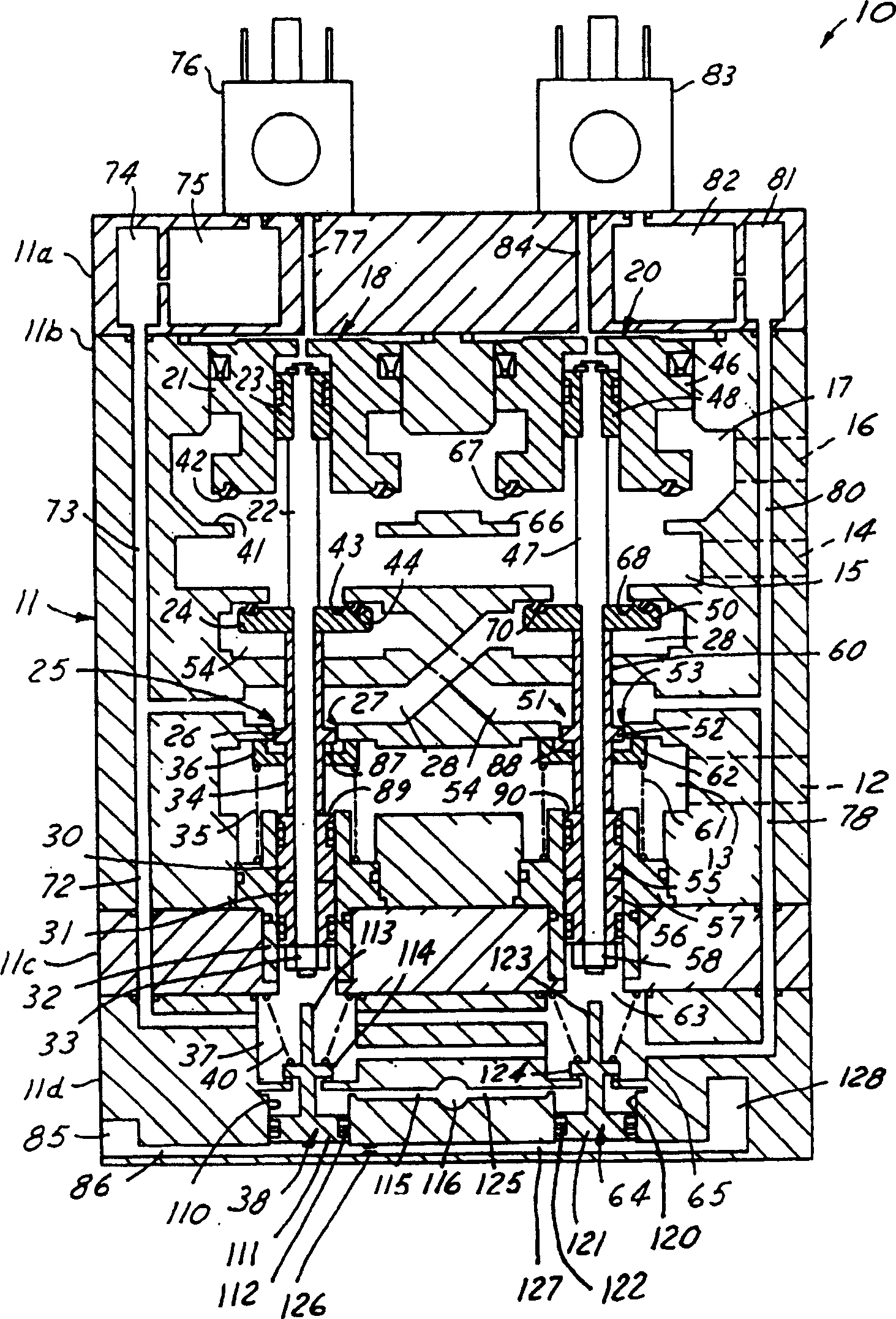
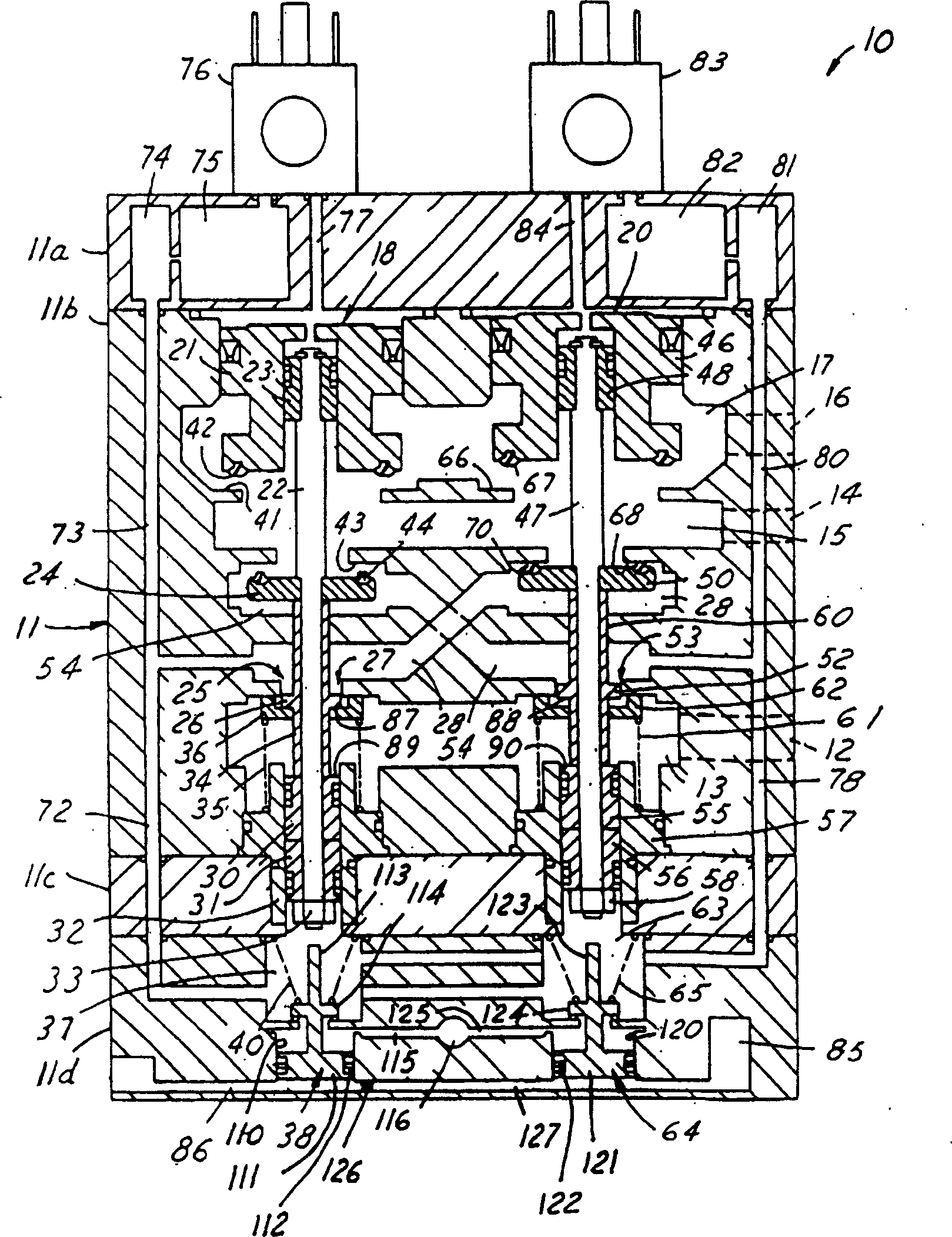
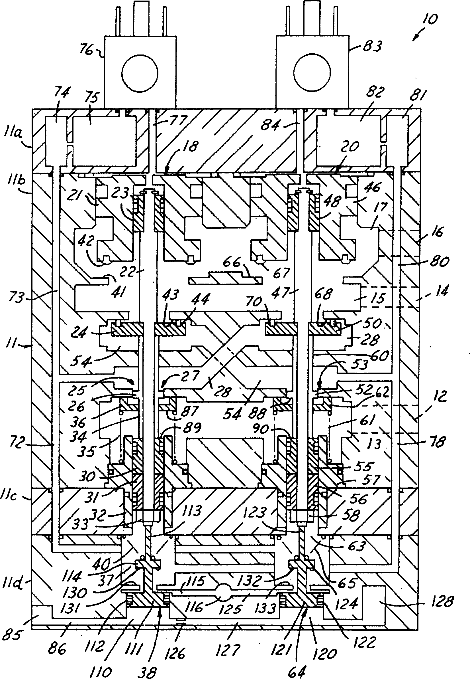
[0016] The following will refer to figure 1 , a control valve system in the form of a double valve 10 comprising a housing 11 with an inlet port 12 leading to an inlet chamber 13, an outlet port 14 leading to an outlet chamber 15 and a discharge port 16 leading to a discharge chamber 17 . Housing 11 may comprise separate blocks 11a-11d, each of which may be clamped or bolted together.

[0017] The chambers 13 , 15 and 17 are connected by a plurality of passages so as to form elongated holes for receiving the first movable valve unit 18 and the second movable valve unit 20 . The first movable valve unit 18 includes a discharge piston / poppet 21 slidably mounted on one end of a valve stem 22 via a piston 23 . The first active valve unit 18 also includes an inlet poppet valve 24 and a restrictor 25 . A disk shoulder 26 projects from a washer 34 secured to the valve stem 22 . Shoulder 26 is slidably received in channel 27 forming flow restrictor 25 , so that pressurized fluid f...


PUM


Abstract

A double valve is reset when a source of pressurized fluid is connected to a reset port. When the source of pressurized fluid is removed from the reset port, a first reset piston is retracted so that a second pilot chamber receives pressurized fluid while a first pilot chamber continues to be vented. A second reset piston is retracted after a predetermined delay time following retraction of the first reset piston, the predetermined delay time being sufficient to allow the second pilot chamber to become substantially pressurized. If a second pilot valve is actuated when the second reset piston is retracted, then the pressurized fluid in the second pilot chamber drives the second movable valve unit out of a deactuated position during a time that pressurized fluid in the first pilot chamber is insufficient to drive the first movable valve unit out of a deactuated position.

Description

technical field [0001] This invention relates generally to control valves, and more particularly to resetting a dual valve for controlling a single flow of pressurized fluid upon simultaneous actuation of a pair of control switches. Background technique [0002] Many machine tools or machine tools are operated by valve systems that interact with pneumatically controlled clutch and / or brake systems. For safety reasons, the control valves used to operate these machine tools require the operator to actuate two separate control switches substantially simultaneously in order to ensure that the operator's hands are clear of the moving parts of the machine tool when the work cycle begins. Typically, an electronic circuit responsive to two control switches generates a pilot control signal applied to a pilot valve to switch the valve's primary fluid circuit, thereby controlling the supply of compressed air (or other fluid) to the machine tool to perform its duty cycle . [0003] Du...

Claims


Application Information

Patent Timeline
Patent Type & Authority Applications(China)
IPC IPC(8): F16K11/04F15B20/00F16P3/22
CPCY10T137/87209F15B20/001F16P3/22Y10T137/0396
Inventor 尼尔·E·拉塞尔约瑟夫·E·福斯特
Owner ROSS OPERATING VALVE CO
Why Eureka
Try Eureka