Pocket telephone
A telephone and portable technology, which is applied in the direction of telephone structure, telephone communication, television, etc.
- Summary
- Abstract
- Description
- Claims
- Application Information
AI Technical Summary
Problems solved by technology
Method used
Image
Examples
no. 1 Embodiment
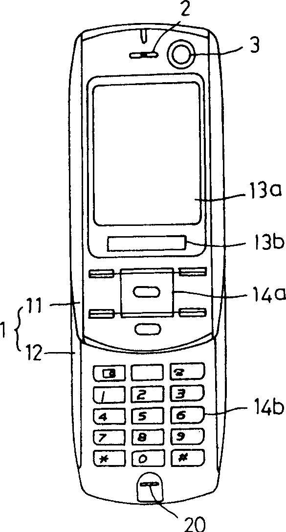
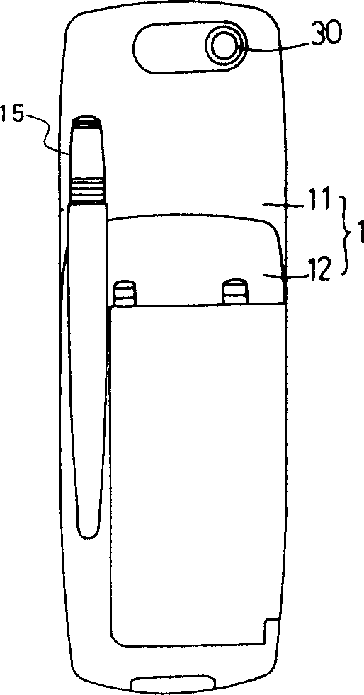
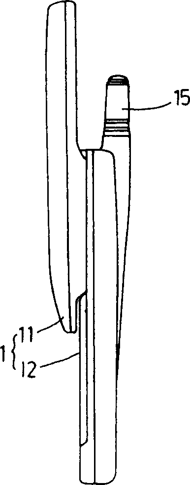
[0041] The portable telephone of the present embodiment looks like Figure 1(a) ~ Figure 1(c) ,as well as Figure 2(a) ~ Figure 2(c) In that way, the shell 1 formed by the shell top 11 and the shell bottom 12 is included, and the shell top 11 and the shell bottom 12 are engaged with each other in a manner that can slide up and down, and can be used as Figure 1(a) ~ Figure 1(c) As shown, the front position of the housing top 11 and the front position of the housing bottom 12 are mutually staggered up and down, which is similar to that of Figure 2(a) ~ Figure 2(c) As shown, the opening and closing operation is performed between the states where the front position of the case top 11 and the front position of the case bottom 12 coincide with each other. Thus, an openable and closable housing 1 is formed.
[0042] On the front of the housing top 11, there is provided a receiver 2 having a speaker inside, and a main display 13a formed of an organic electroluminescent display and...
no. 2 Embodiment
[0058] The portable telephone of the present embodiment looks like Figure 5 6(a) and 6(b), it includes a flat main body shell 41 and a cover shell 42, and the top end of the main body shell 41 and the bottom end of the cover shell 42 are connected by a hinge mechanism 43. interconnected, like Figure 5 As shown, the opening and closing operation can be performed between the state where the lid case 42 is opened and the state where the lid case 42 is closed as shown in FIGS. 6( a ) and 6 ( b ). In this way, a foldable casing is formed.
[0059] On the front of the main body case 41, a key input device 45 formed of a plurality of operation keys is provided, and at the bottom end of the front, a microphone 46 is provided. In addition, a retractable antenna 44 is provided on the back of the main body case 41 .
[0060] On the other hand, a main display 47a is provided on the front surface of the cover case 42, and a receiver 48 having a speaker inside is provided at the front ...
no. 3 Embodiment
[0072] The portable telephone of the present embodiment looks like Figure 8 and Figure 9 As shown, it includes a flat case 6 formed by combining a front case 61 and a rear case 62 , and an antenna 63 protrudes from the head of the case 6 . On the surface of the front case 61, a key input device 66 and a display 67 formed of a plurality of operation keys are provided. Also, at the front end portion of the surface of the front case 61, a receiver 64 with a speaker built in is provided, and at the bottom end thereof, a transmitter 65 with a microphone built therein is provided. In addition, CCD imaging devices 7 and 70 are provided on the front end portions of the surfaces of the front case 61 and the rear case 62 .
[0073] In the mobile phone of this embodiment, a video mode that can record moving pictures and sounds can be set, and the sensitivity of the microphone can be switched according to the following two levels of levels that are suitable for calls. Normal level, a...
PUM
 Abstract
Description
Claims
Application Information
 - R&D
- Intellectual Property
- Life Sciences
- Materials
- Tech Scout
- Unparalleled Data Quality
- Higher Quality Content
- 60% Fewer Hallucinations
Browse by: Latest US Patents, China's latest patents, Technical Efficacy Thesaurus, Application Domain, Technology Topic, Popular Technical Reports.
© 2025 PatSnap. All rights reserved.Legal|Privacy policy|Modern Slavery Act Transparency Statement|Sitemap|About US| Contact US: help@patsnap.com


