Face and side cutter

A technology of three-sided cutting edge and milling cutter, which is applied in the direction of milling cutters, milling machine equipment, manufacturing tools, etc., can solve the problems of difficult control of precision, time-consuming and inconvenient, and achieve high precision and easy and reliable adjustment

Active Publication Date: 2005-03-23
ZHUZHOU HARD ALLOY GRP CO LTD
View PDF1 Cites 21 Cited by
  • Summary
  • Abstract
  • Description
  • Claims
  • Application Information

AI Technical Summary

Problems solved by technology

However, this kind of milling cutter has no special adjustment structure, and the width of the cutting edge must be adjusted by tapping the left and right tool holders bit by bit axially to achieve the purpose of adjusting the width of the milling groove or incision, which is time-consuming and inconvenient. Accuracy is difficult to control

Method used


Image

  • Face and side cutter
  • Face and side cutter
  • Face and side cutter

Examples


Embodiment Construction

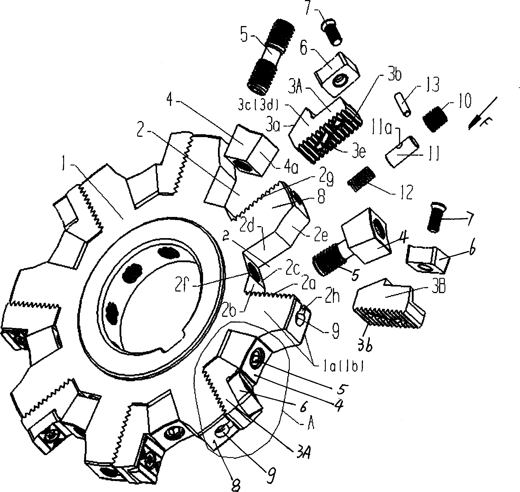
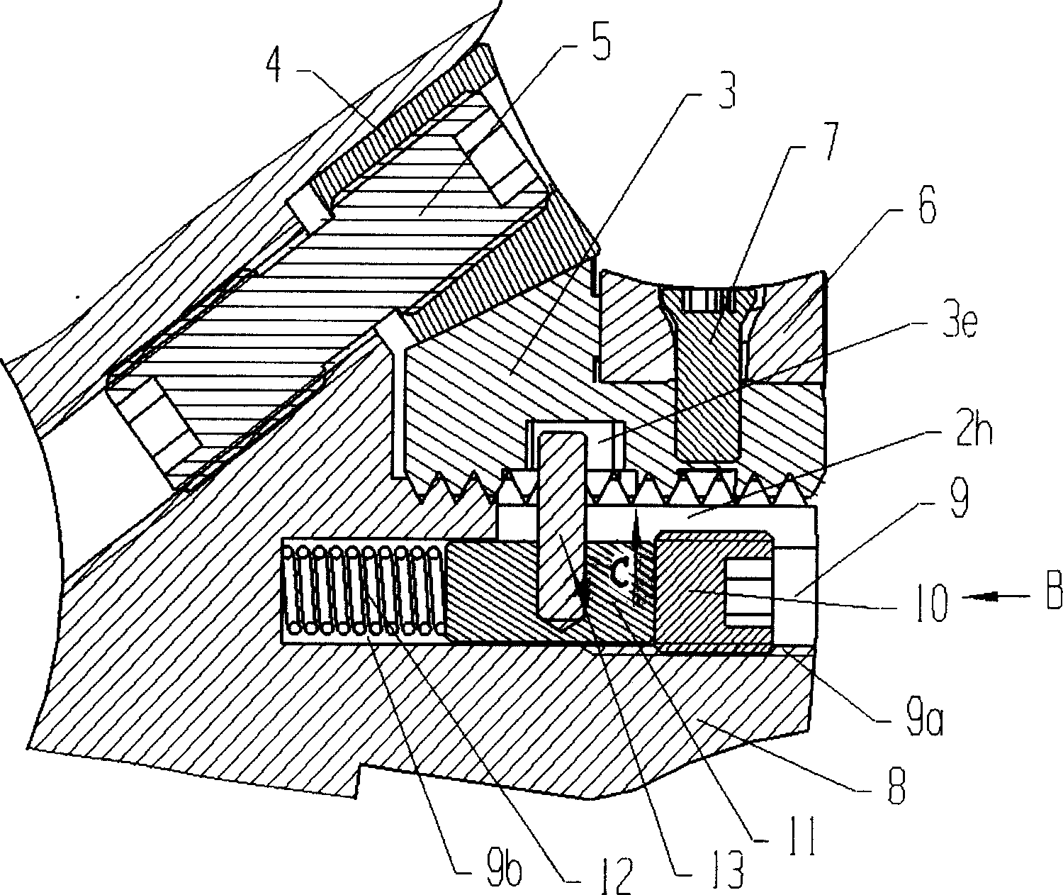
[0014] like Figure 1-Figure 2 As shown, the three-sided edge milling cutter of the present invention includes a disk 1 with chip pockets 2 distributed at intervals around the periphery, and is divided into left and right tool seats 3A, 3B, which are placed in the chip pockets 2 at intervals, and the screws 7 can be Fix the blade 6 on the tool seat 3A, 3B; the chip flute 2 is sequentially connected by a serrated surface 2a, three straight surfaces 2b, 2c, 2d and an arc surface 2e, and the serration surface 2a and the arc surface 2e are respectively It is connected to the outer edge of the disc 1; the bolt 5 is screwed on the disc 1 through the central threaded through hole of the pressing block 4 and the threaded through hole 2f on the second straight surface 2c of the chip flute 2, so that the inclined plane of the pressing block 4 4a presses the inclined surfaces 3a of the knife holders 3A, 3B, thereby wedging and fixing the knife holders 3A, 3B. The sawtooth surface 3b of ...


PUM


Abstract

A milling cutter with three cutting edges and adjustable milled width is composed of circular disk with chip flutes on its periphery, left and right cutted holders in said chip flutes, pressing blocks, stud screw bolts, cutting blades and screws for fixing said cutting blades.

Description

technical field [0001] The present invention relates to a three-sided edge milling cutter, which comprises a disc, and forms a plurality of chip pockets distributed tangentially at intervals along the periphery of the disc, and a tool seat of an indexable cutting insert is arranged in the chip pocket, The cutting blades are alternately arranged on the left and right tool holders, and the width of the superimposed cutting edges is greater than the thickness of the disc, so that the three-sided edge milling cutter mills a groove or cut defined by two parallel sides and a bottom surface. Background technique [0002] In the existing three-sided edge milling cutter, such as US Patent 5,395,186 (US005395186A, Mar, 7, 1995), it adopts a tool seat structure with guiding serrations, which can move the tool seat in the axial direction to adjust the milling groove or cut At the same time, there is a small round or rectangular slot at the bottom of the chip pocket, and the pin at the b...

Claims


Application Information

Patent Timeline
IPC IPC(8): B23C5/22
Inventor 马晓魁姜涛李屏王社权
Owner ZHUZHOU HARD ALLOY GRP CO LTD
Why Eureka
Try Eureka