
Light source for optical encoder

An optical encoder and optical encoding technology, which is applied in the field of optical encoder light sources that can improve the interference of close strong light, can solve the problems of being unable to effectively solve the interference of close strong light and unable to drop to the trough

Inactive Publication Date: 2005-03-30
OPTINDEX
View PDF0 Cites 8 Cited by
  • Summary
  • Abstract
  • Description
  • Claims
  • Application Information

AI Technical Summary

Problems solved by technology

However, due to the problem of close to strong light interference, the actual measured signal will be as shown by the dotted line, which will be interfered by strong light and cannot drop to the trough
[0005] Figure 5 Shown is a side view of another known optical encoder 110. In order to solve the above problems, a light-shielding sheet 116 can be added in front of the photodetector 114B to cover the part between the two light-receiving surfaces. However, due to the fluctuation of light characteristics, still can not effectively solve the problem of interference from strong light

Method used


Image

  • Light source for optical encoder
  • Light source for optical encoder
  • Light source for optical encoder

Examples


Embodiment Construction

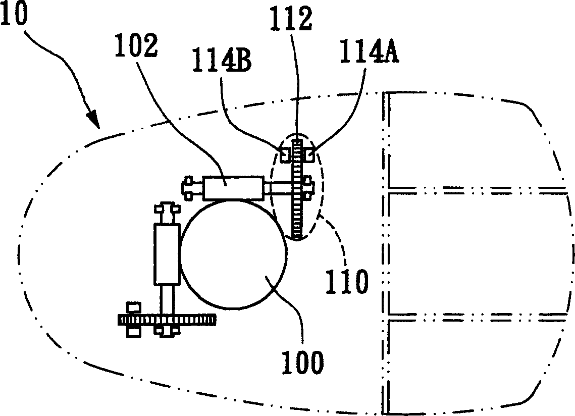
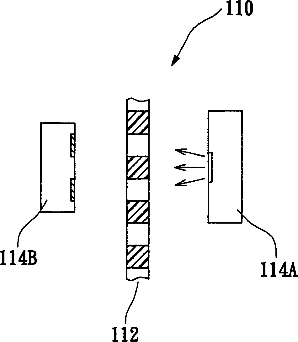
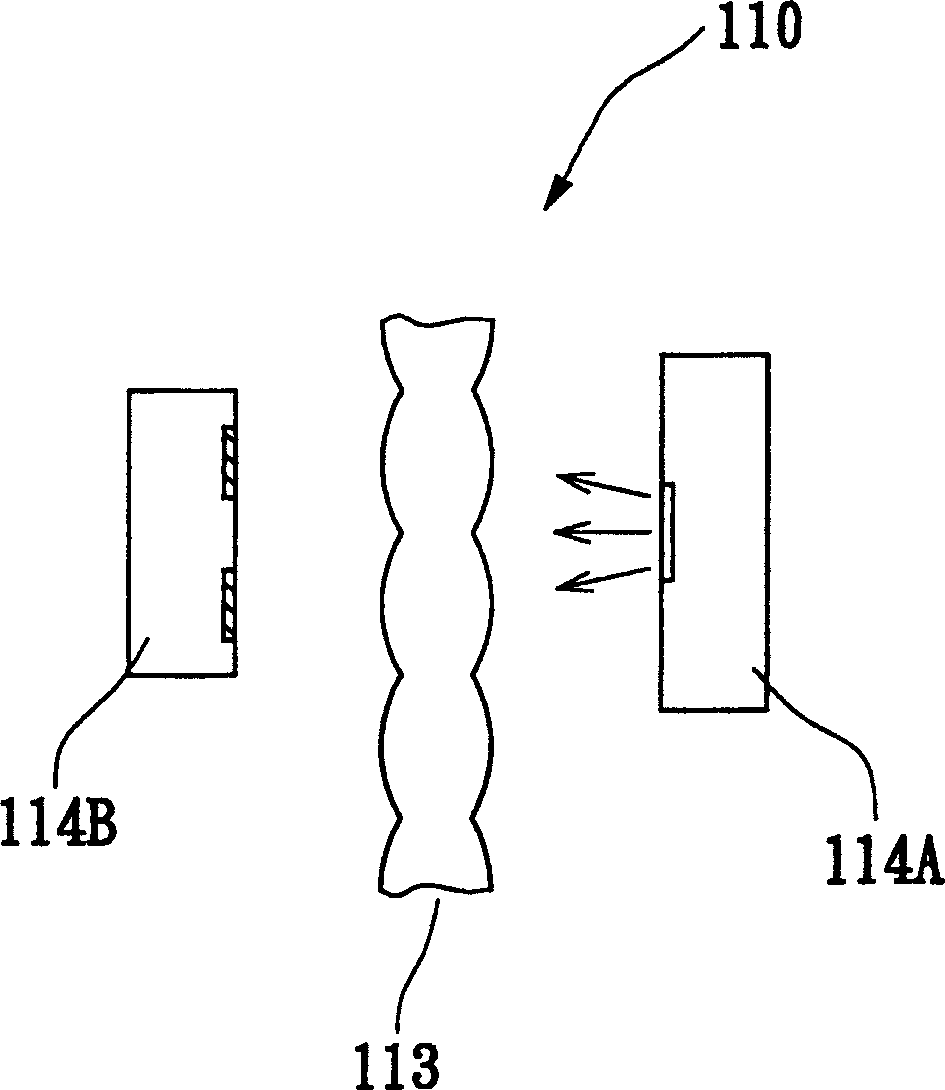
[0025] Such as Figure 6A Shown is a schematic diagram of the first preferred embodiment of the optical encoder light source of the present invention. The optical encoder 210 of the present invention also has a light source 214A, a light detector 214B mainly has two light-receiving surfaces (hatched parts), and a code wheel 212 can intermittently block the light emitted by the light source 214A to distinguish a roll The moving direction and displacement of the ball, since the photodetector 214B and the code wheel 212 are known technologies, will not be repeated here.

[0026] As shown in this figure, the light source 214A includes a light emitting diode 2140 and a packaging case 2142 , the packaging case 2142 has a corresponding light-receiving surface and a light alignment unit 2144 integrally formed with the packaging case 2142 . The light alignment unit 2144 may include two plano-convex lenses or two bi-convex lenses to align the light emitted by the LED 2140 to the two li...


PUM


Abstract

The invention relates to an optical encoder light source. Said optical encoder includes a photodetector with several light-receiving surfaces and a encoding wheel capable of discontinuously rupturing light sent from light source. Said light source includes at least a light-emitting diode, a package shell body and an alignment unit. It also has a prism correspondent to light-receiving surfaces. Said alignment unit is assembled on said package shell body or said alignment unit and package shell body can be integrated into form. Said lens is planocovex lens or bicovex lens, can be effectively aligned with said light source and can improve the problem of proximity highlight interference.

Description

technical field [0001] The invention relates to a light source for an optical encoder, in particular to a light source for an optical encoder that can improve the interference of close strong light. Background technique [0002] Along with the progress of computer software and popularization of graphical user interface, the mouse has been widely used in the user interface of the computer. A known mouse (such as a mechanical mouse) uses a rolling ball to cooperate with an optical encoder to achieve the function of controlling the cursor on the computer screen. see figure 1 , is a top view of a known mechanical mouse 10 , the mechanical mouse 10 mainly has a roller ball 100 , at least one roller 102 and a corresponding optical encoder 110 . The optical encoder 110 includes an encoder wheel 112 (encoder wheel) that is coupled with the roller 102, and optical components on both sides of the encoder wheel 112, which include a light source 114A and a light detector 114B. The ro...

Claims


Application Information

Patent Timeline
IPC IPC(8): G01D5/26
Inventor 吕淑芬
Owner OPTINDEX
Learn More