
LED Light Source and backlight modular

A technology of LED light source and backlight module, which is applied in the direction of optics, diffraction grating, nonlinear optics, etc., can solve the problems of non-adjustable and inconvenient light-emitting angles of finished products, and achieve the effects of convenient control, improved light uniformity, and reduced optical dark areas

Inactive Publication Date: 2005-03-30
HONG FU JIN PRECISION IND (SHENZHEN) CO LTD +1
View PDF0 Cites 10 Cited by
  • Summary
  • Abstract
  • Description
  • Claims
  • Application Information

AI Technical Summary

Problems solved by technology

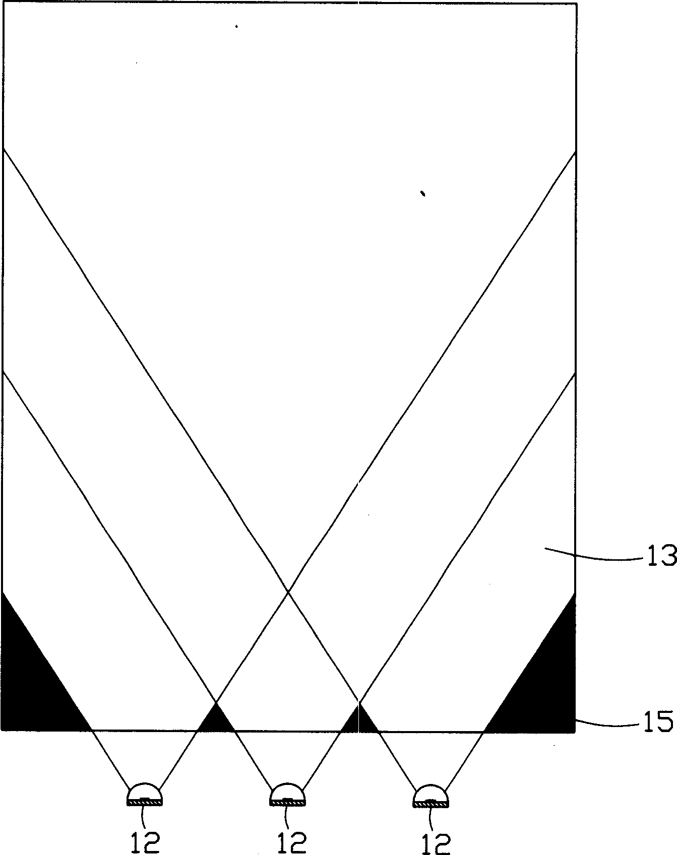
However, the luminous angle of LED is limited by its own packaging design (Layout) and manufacturing process, and the luminous angle of the finished product cannot be adjusted, which is inconvenient in actual use.

Method used


Image

  • LED Light Source and backlight modular
  • LED Light Source and backlight modular
  • LED Light Source and backlight modular

Examples


Embodiment Construction

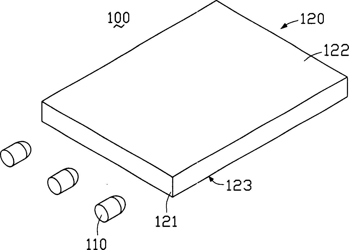
[0015] figure 2 It is a three-dimensional schematic view of the backlight module of the present invention, and the backlight module 100 includes a plurality of LED light sources 110 and a light guide plate 120 . The LED light source 110 is used to emit light beams, and the light guide plate 120 guides the transmission direction of the light beams emitted by the light source 110, and converts them into surface light sources for emission.

[0016] The light guide plate 120 is a flat light guide plate, which includes a light incident surface 121 , a light exit surface 122 connected to the light incident surface 121 , and a bottom surface 123 opposite to the light exit surface 122 . The light incident surface 121 receives the light beam emitted by the LED light source 110, the light exit surface 122 can be processed into a rough surface with a certain roughness, and the bottom surface 123 can be provided with a plurality of dots (not shown in the figure) and a plurality of V-shap...


PUM


Abstract

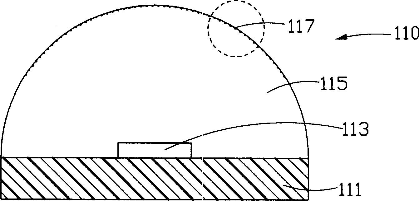
The invention provides a LED light source whose light-emitting angle is larger and can be regulated and backlight module by adopting said LED light source. Said invented backlight module includes a light-conducting plate and at least a LED light source, Said light-conducting plate includes at least one light-incoming surface. and said LED light source includes a base, a light-emitting chip and a package resin. Said package resin can be used for covering said light-emitting chip and can be formed into a light-outcoming surface, said ligh-outcoming surface and light-incoming surface of the ligh-conducting plate are oppositely placed-in which said LED light source further includes a diffraction grating placed in its light-outcoming surface position. The optical diffraction effect produced when the light beam sent from LED light-emitting chip is out come by means of diffraction grating can make its light-emitting angle be enlarged so as to reduce optical dark region of light-incoming side of the light-conducting plate and raise light-outcoming uniformity of backlight module, to reduce optical dark region of light-incoming side of the light-conducting plate and raise light-outcoming uniformity of backlight module.

Description

【Technical field】 [0001] The invention relates to a backlight module for a liquid crystal display, in particular to an LED light source and a backlight module using the LED light source. 【Background technique】 [0002] Due to the advantages of lightness, thinness, and low power consumption, liquid crystal displays are widely used in modern information equipment such as notebook computers, mobile phones, and personal digital assistants. Since the liquid crystal itself does not have light-emitting properties, it is necessary to provide a backlight module for it to realize the display function. [0003] The prior art backlight module includes a light source and a light guide plate. The light source is arranged relative to the light incident surface of the light guide plate. The light guide plate guides the transmission direction of the light beam emitted by the light source and converts the line light source or point light source into a surface light source to emit. The bottom...

Claims


Application Information

Patent Timeline
IPC IPC(8): G02B5/18G02F1/13357H01L33/00
Inventor 吕昌岳黄文正林志泉
Owner HONG FU JIN PRECISION IND (SHENZHEN) CO LTD
Learn More