Current to voltage conversion circuit for photo detector integrated circuit employing gain switching circuit

A technology of voltage conversion circuit and gain switching, which is applied in the directions of gain control, electric variable adjustment, negative feedback circuit layout, etc. It can solve the problems of feedback resistance reducing response speed and deteriorating noise characteristics, etc.

Inactive Publication Date: 2005-04-06
SAMSUNG ELECTRO MECHANICS CO LTD
View PDF1 Cites 14 Cited by
  • Summary
  • Abstract
  • Description
  • Claims
  • Application Information

AI Technical Summary

Problems solved by technology

However, in a method similar to that previously described with reference to Figure 3, the feedback resistor reduces the overall response speed and deteriorates its noise characteristics

Method used


Image

  • Current to voltage conversion circuit for photo detector integrated circuit employing gain switching circuit
  • Current to voltage conversion circuit for photo detector integrated circuit employing gain switching circuit
  • Current to voltage conversion circuit for photo detector integrated circuit employing gain switching circuit

Examples


Embodiment Construction

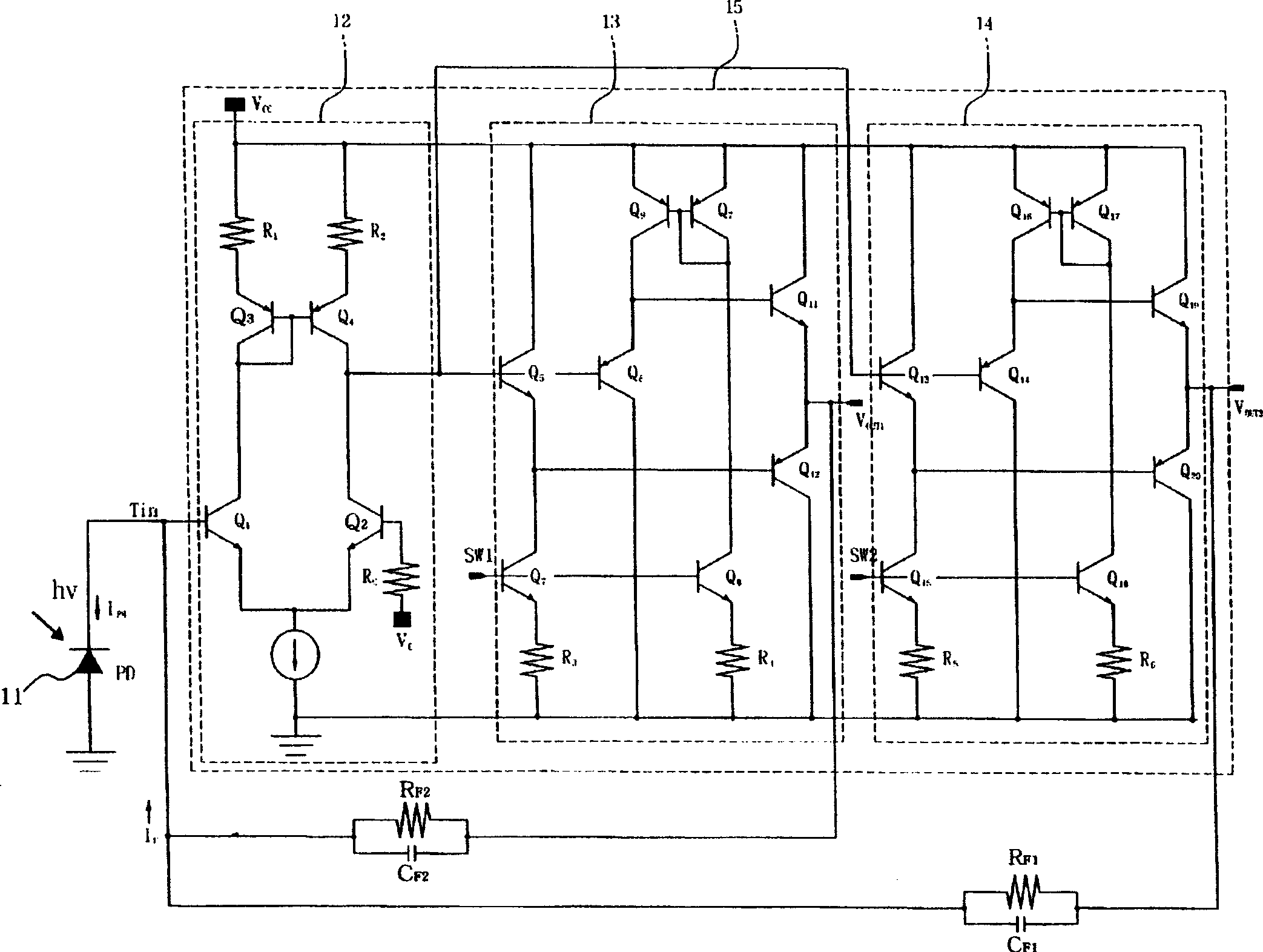
[0041] Figure 4 A circuit diagram showing a current-to-voltage conversion circuit structure using a gain switching circuit according to a preferred embodiment of the present invention.

[0042] exist Figure 4 , current mirror 42 provides transistor Q S , Q T1 and Q T2 , and make it suitable to transfer the current generated in the photoelectric conversion device 41 to the read connection transistor Q by reflection 5 and write connection transistor Q 9 middle.

[0043] If an optical signal is input to a photoelectric conversion device 41, such as a photodiode, a current I proportional to the input light intensity is generated in the device 41. PH . The resulting current I PH flows from the emitter of transistor Qs to its collector, and flows through transistor Qs with S A current of almost equal value flows through transistor Q T1 and Q T2 in each. In read mode, by transistor Q S and Q T1 composed of a current mirror connected to the read transistor Q 5 supply cu...


PUM


Abstract

A current to voltage conversion circuit for improving the speed of a photoelectric conversion device and frequency characteristics of an amplifier by improving a method for switching the gain of an amplification circuit for a photo detector integrated circuit (PDIC). Photocurrent generated in the photoelectric conversion device, such as a photodiode, is transferred to the amplifier by means of current mirroring, so as to raise a bias voltage to the photoelectric conversion device and enhance a response speed thereof. Further, the amount of current generated in the photoelectric conversion device is adjusted through control of a resistance ratio of a current mirror circuit. Therefore, a fixed feedback resistor can be used for the amplifier irrespective of modes, so as to enhance frequency characteristics of the amplifier.

Description

[0001] Related Application Cross Reference [0002] The claims of this application benefit from Korean Patent Application No. 2003-68413 filed on October 1, 2003 with the Korean Intellectual Property Office. The disclosure thereof is hereby cross-referenced. technical field [0003] The present invention relates to a current-to-voltage conversion circuit for use on a photodetector integrated circuit (PDIC) using a gain switching circuit. [0004] More particularly, the present invention relates to a current-to-voltage conversion circuit that increases the speed of a photoelectric conversion device and improves frequency characteristics of an amplifier by improving a method for switching gain of the amplifier circuit on a PDIC. Among them, a photocurrent generated in a photoelectric conversion device such as a photodiode is transferred to an amplifier through a current mirror, thereby raising the bias voltage of the photoelectric conversion device and improving its response sp...

Claims


Application Information

Patent Timeline
Patent Type & Authority Applications(China)
IPC IPC(8): G11B7/13G05F3/26G11B7/0045G11B7/005G11B7/125H02M11/00H03F1/34H03F3/08H03F3/45H03G3/12H03G3/30
CPCH03G3/3084H03F2203/45526H03F3/4508H03F1/34H03F3/087H03F3/08
Inventor 金尚硕权敬洙河昌佑孔正喆
Owner SAMSUNG ELECTRO MECHANICS CO LTD
Why Eureka
Try Eureka