

Flapping wing for ornithopter
An aircraft and square frame technology, which is applied in the field of aircraft flapping wings, can solve problems such as failure to form and unsatisfactory effects, and achieve the effect of saving energy and reducing energy consumption
Inactive Publication Date: 2005-04-27
余志鹏
View PDF0 Cites 30 Cited by
- Summary
- Abstract
- Description
- Claims
- Application Information
AI Technical Summary
Problems solved by technology
Since a considerable part of the middle part of the bird's wing is where the meat membrane or feathers are concentrated, this part cannot form a "contrast force" when swinging up and down, and the effect is still not very ideal.
Method used
View moreImage
Smart ImageViewing Examples

Examples
Embodiment Construction
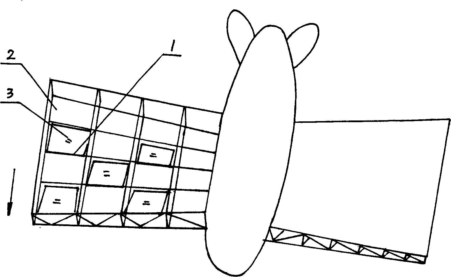
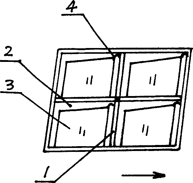
[0008] The flapping wing of an aircraft is a double-layer inclined truss structure, which is made of aluminum alloy material with high strength and light specific gravity. The thickness of one end connected to the aircraft body is greater than that of the other end. Frame 2, each square frame 2 is provided with a feather plate 3, the front end of the feather plate 3 is flexibly connected with the horizontal frame edge in the square frame 2 through the hook 4 at the end, the feather plate 3 can seal the square frame .
Login to View More PUM
 Abstract
The flapping wing for ornithopter is one double-layer inclined truss structure, and has the end connected to the ornithopter with greater thickness, low layer separated with the truss into homogeneously distributed square frames, and wing sheets fixed to the frames and capable of sealing the square frames. The flapping wing is connected to the ornithopter body via the connecting rotation shaft. The wing sheets are slightly opened normally, when the flapping wing is raised, the wing sheets are opened to reduce resistance, and when the flapping wing moves downwards, the wing sheets seal the square frames to form great upward support force. When the flapping wings swing up and down, great 'differential force' may be produced to reduce power consumption.
Description
technical field [0001] The invention relates to an aircraft flapping wing. Background technique [0002] The orthopter is one of the oldest models ever conceived, and it belongs to bionics. Due to the large weight of human beings and the relatively weak strength of hands and feet, this bird-like orthopter is only a fantasy. The flapping wings designed by some people are all in the shape of a whole cloth bag, and the "contrast force" is extremely small when the upward and downward force is exerted. It is difficult to achieve the purpose of lift-off. We have observed that there is a bony rod in the bird's feathers, and there are whole rows of neatly arranged hair rods on both sides, but one thing people ignore is that it is slightly curved. When the bird's wings are lifted up, the airflow will bend it When the angle becomes larger, the resistance decreases, and when it is pressed down, its feathers become flattened, thereby increasing its uplifting force, so birds can fly w...
Claims
Login to View More Application Information
Patent Timeline
 IPC IPC(8): B64C33/02
Inventor余志鹏
Owner余志鹏