
Internal illuminating lamp

一种照明灯、内室的技术,应用在其他车辆内部照明、车辆内部照明装置、照明装置等方向,能够解决成本提高、结构复杂、数量增加等问题,达到简单结构和、高耐用性、避免元件数量增加的效果

Active Publication Date: 2005-04-27
YAZAKI CORP
View PDF1 Cites 2 Cited by
  • Summary
  • Abstract
  • Description
  • Claims
  • Application Information

AI Technical Summary

Problems solved by technology

However, in this case, the number of parts increases, so the cost increases accordingly, and the structure becomes complicated

Method used


Image

  • Internal illuminating lamp
  • Internal illuminating lamp
  • Internal illuminating lamp

Examples


Embodiment Construction

[0031] Referring to the drawings, an embodiment of the present invention will be described.

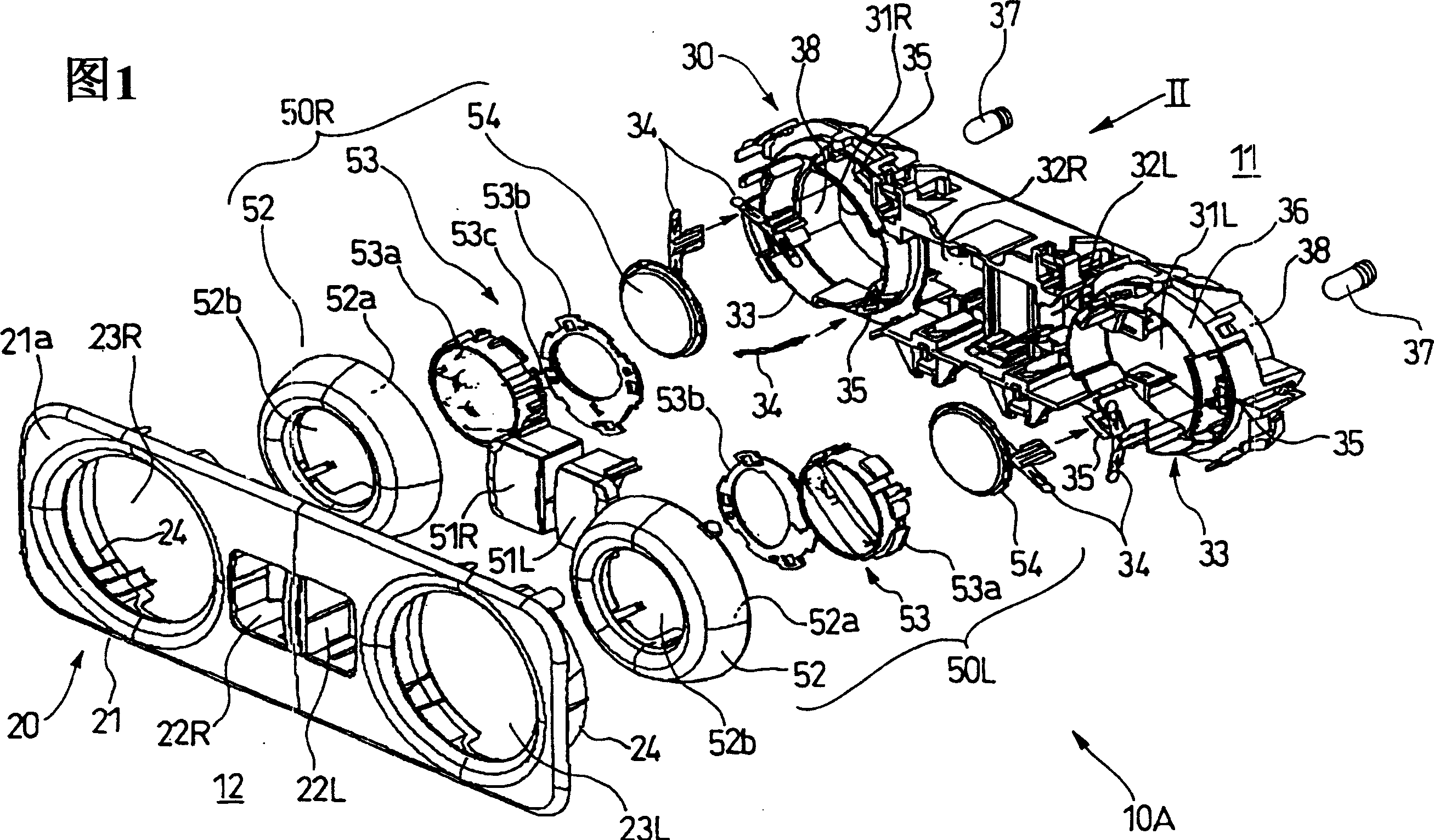
[0032] As shown in FIG. 1 , an interior lighting lamp 10 according to an embodiment of the present invention includes a decorative element 20 (such as Figure 7 shown), and the functional body 30 located inside the decorative element 20, which serves as the main body, on which different electronic components are installed.

[0033] Such as Figure 7 As shown, in the structure of the interior lighting lamp, the decorative element 20 is arranged in the interior material (interior trim) 13 in the vehicle body 11, so it can be conveniently connected in advance in the harness W / H arranged on the back of the interior material .

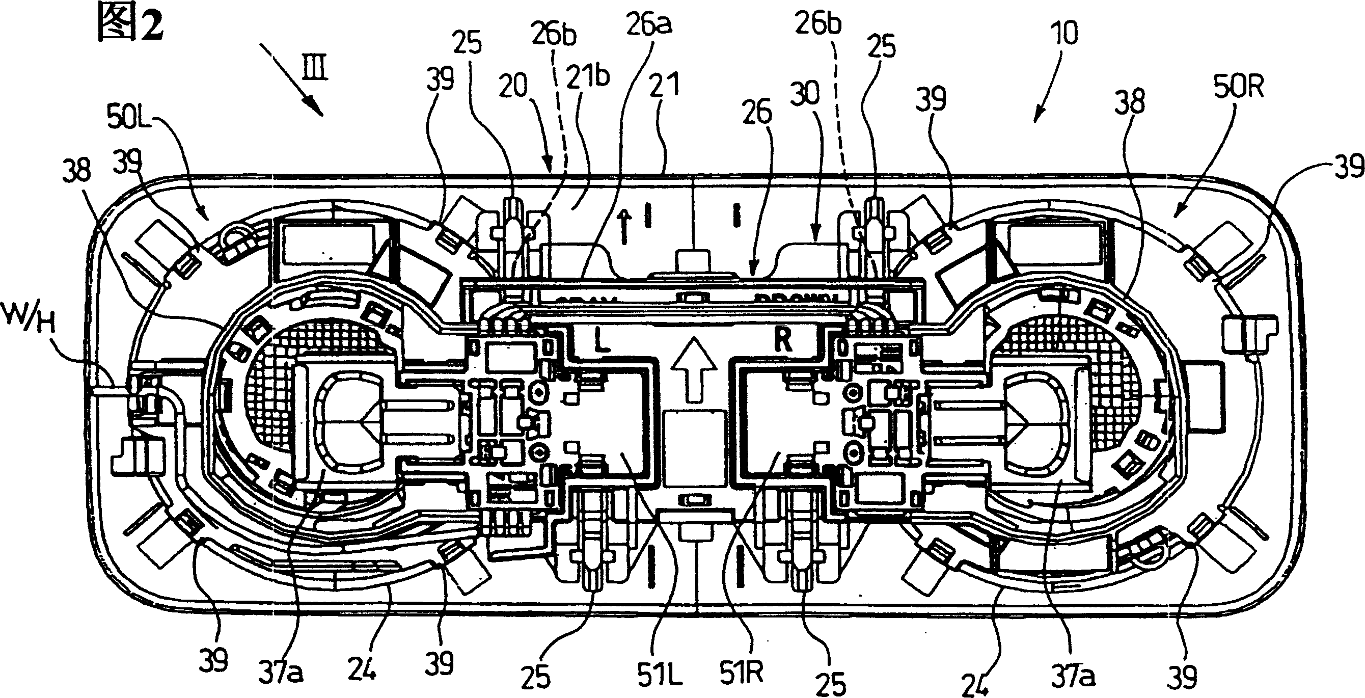
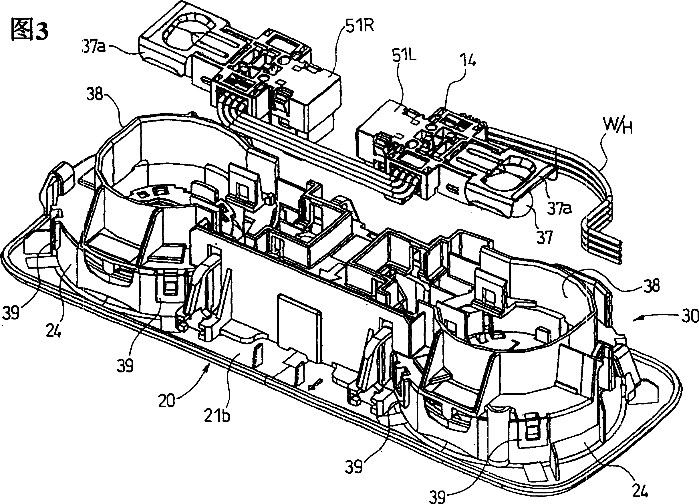
[0034] As shown in FIGS. 1 to 3 , the decorative element 20 has a surface 21 a exposed to the chamber 12 and includes, for example, a frame 21 forming a square. Switch holes 22L, 22R are provided at the center of the frame 21 for exposing the left and right swit...


PUM


Abstract

A bezel member ( 52 ) to which a lens ( 54 ) which transmits light from a light source ( 37 ) is supported on a main body ( 30 ) to be fixed to a vehicle body ( 11 ). A spherical surface ( 52 a) is formed on one of the main body ( 30 ) or a bezel member ( 52 ), and sliding members ( 34 ) for being pressed against the spherical surface ( 52 a) are formed on the other one of them, so that the bezel member ( 52 ) can be rotated with respect to a supporting member ( 33 ) of the main body ( 30 ) and fixed to a given position. Since a metal plate is used as the sliding members ( 34 ) in this interior illumination lamp ( 10 ), a problem such that the light source cannot be fixed to the desired direction due to abrasion or change of properties of the felt sliding member as in the related art due to the temperature or deterioration with age can be solved. Also, in comparison with the case in which the spring or the like is employed, increase in cost due to increase in the number of parts can be avoided.

Description

technical field [0001] The present invention relates to an interior lighting lamp, for example, to an interior lighting lamp mounted on a door, roof or other part of an automobile. Background technique [0002] In related technologies, such as Figure 10 The interior lighting lamp is shown, for example, in Unexamined Japanese Patent No. 2000-1141. [0003] The interior light is installed on the rear door of the tourist vehicle, and is suitable for illuminating the luggage rack located at the rear of the tourist vehicle by changing the lighting direction. [0004] Such as Figure 10 As shown, the interior lighting lamp 100 includes a lamp housing 102 mounted on a decoration 101 forming the wall of the rear door, and a circular opening 103 is formed at the front of the lamp housing 102 . The lamp supporting portion 104 has a spherical inner surface, and is provided at the rear of the opening 103 (at the Figure 10 The right side of the lamp body 105, which is partially spheri...

Claims


Application Information

Patent Timeline
Patent Type & Authority Applications(China)
IPC IPC(8): B60Q3/02B60Q3/06F21V21/30F21W106/00
CPCF21V21/30B60Q3/0253B60Q3/06B60Q3/30B60Q3/44
Inventor 铃木宏幸石井公启木村太弥安藤浩士
Owner YAZAKI CORP
Learn More