
Method and apparatus for generating shadow effect using shadow space

A shadow and space technology, applied in the field of computer graphics system, can solve the problem of memory bandwidth inefficiency and so on

Active Publication Date: 2005-04-27
VIA TECH INC
View PDF0 Cites 12 Cited by
  • Summary
  • Abstract
  • Description
  • Claims
  • Application Information

AI Technical Summary

Problems solved by technology

To use an 8-bit pattern value in the accept state, the entire 32-bit Z / pattern value must be read out, making memory bandwidth use very inefficient

Method used


Image

  • Method and apparatus for generating shadow effect using shadow space
  • Method and apparatus for generating shadow effect using shadow space
  • Method and apparatus for generating shadow effect using shadow space

Examples


Embodiment Construction

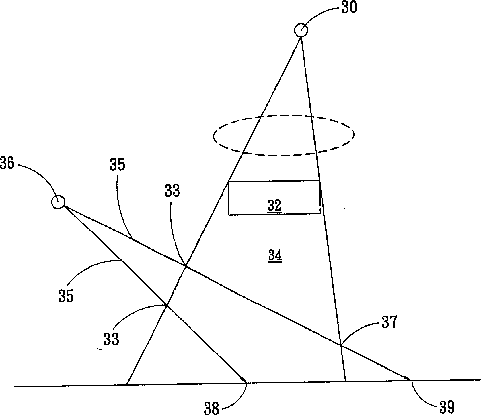
[0039] The direction of the present invention discussed here is a device, system and method for generating shadow effects in a computer graphics system. In order that the present invention can be thoroughly understood, the detailed construction will be set forth in the following description. Obviously, the practice of the invention is not limited to specific details familiar to those skilled in lighting devices. In other instances, well-known compositions or process steps have not been described in detail in order to avoid unnecessarily limiting the invention. The preferred embodiments of the present invention will be described in detail as follows, but in addition to these detailed descriptions, the present invention can also be widely implemented in other embodiments, and the scope of the present invention is not limited, it is based on the following scope of the invention .

[0040] Fig. 4 has enumerated the basic element of some specific embodiments of the present invent...


PUM


Abstract

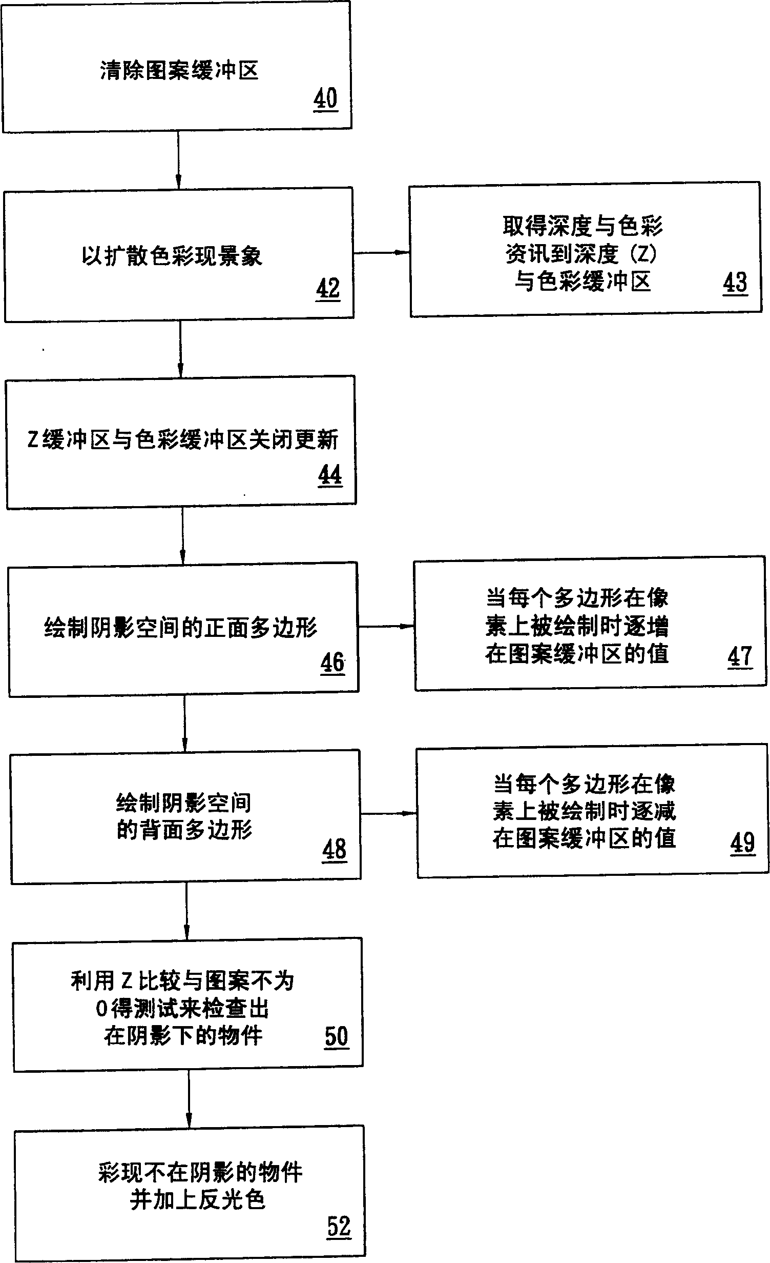
The computer graphics system is configured to generate a shadow effect with a stencil shadow volume method using a combination of compressed and uncompressed stencil buffers in coordination with compressed and uncompressed depth data buffers. An uncompressed stencil buffer is capable of storing stencil shadow volume data for each pixel and a compressed stencil buffer is capable of storing stencil shadow volume data for a group of pixels.

Description

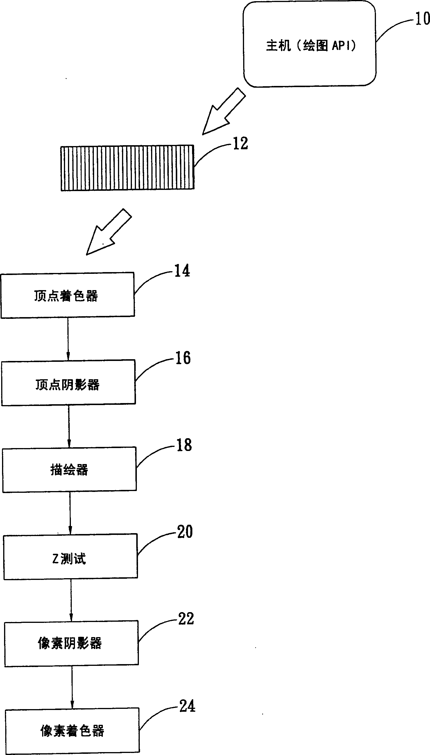
technical field [0001] The present invention relates to a computer graphics system, in particular to a method and device for generating shadow effects using a shadow volume method. Background technique [0002] As generally known, 3D computer graphics is concerned with the generation or rendering of a 2D image of a 3D object for display or presentation on a display device or monitor such as a cathode ray tube or liquid crystal display. Objects can be simple geometry primitives such as points, line segments, triangles, or polygons. More complex objects can be rendered on a display device by representing a series of connected planar polygons, such as a series of connected planar triangles. All geometric units can ultimately be described as a vertex or a set of vertices, such as coordinates (x, y, z) to define a point, such as the endpoint of a line segment or a corner of a polygon. [0003] The vertices of these shapes are processed in a series of operations or processing st...

Claims


Application Information

Patent Timeline
Patent Type & Authority Applications(China)
IPC IPC(8): G06F13/00G06T15/00G06T15/60
CPCG06T15/005G06T15/60
Inventor 徐建明陈文中王渊峰李亮约翰布拉德氏柏瑞斯·柏克潘克
Owner VIA TECH INC
Learn More