

Braker for shuttle of tubular knitting machine
A technology for brakes and circular looms, applied to circular looms, looms, textiles, etc., can solve the problems of complicated manufacturing process of two-way springs, troublesome replacement and installation, unfavorable promotion and use, etc.
Inactive Publication Date: 2005-05-11
新昌县宝妮纺织服饰有限公司
View PDF1 Cites 2 Cited by
- Summary
- Abstract
- Description
- Claims
- Application Information
AI Technical Summary
Problems solved by technology
[0002] The existing brakes for the shuttles of circular looms are composed of tension discs, tension disc supports, small shafts, extension spring shafts, extension springs, extension spring frames, etc., with many components and many moving points, and all parts are easy to wear and tear. Short lifespan, need to be replaced often, and troublesome when replacing a new installation
Chinese Patent Announcement No. CN2033406U, Announcement date March 1, 1989, the disclosed circular loom shuttle uses a brake to install a movable support on the shaft, and adopts a two-way spring, which simplifies the structure and improves the service life, but in practical application There are still problems of uneven braking force and troublesome installation, especially after the spring is damaged, it is very troublesome to replace, the shaft must be disassembled, and the manufacturing process of the two-way spring is complicated, which is not conducive to popularization and use.
Method used
View moreImage
Smart ImageViewing Examples

Examples
Embodiment Construction
[0012] The present invention will be further described in detail below in conjunction with the accompanying drawings and specific embodiments.
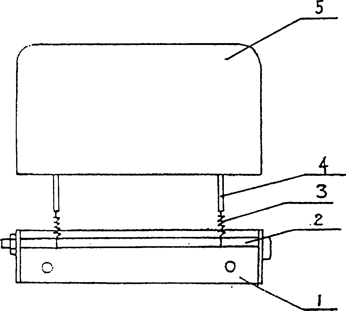
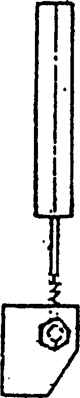
[0013] In the brake for a circular loom shuttle of the present invention, the shaft 2 is installed on the base 1, and two springs 3 with the same diameter and the same elastic coefficient are respectively hung on the shaft 2 through a hook at one end, and can freely rotate around the shaft. The material of spring 3 can be selected 45 steels for use, and the hook of spring 3 other ends is hung on the support 4 that connects double-sided cowhide 5 respectively.
Login to View More PUM
 Abstract
A brake for the shuttle of circular loom is composed of base, axle fixed to base, spring installed to axle, supporter and dual-surface ox leather fixed to the top end of said supporter. Its advantages are convenient exchange and high braking effect.
Description
technical field [0001] The invention relates to a braking device, in particular to a braking device for a shuttle of a circular loom. Background technique [0002] The existing brakes for the shuttles of circular looms are composed of tension discs, tension disc supports, small shafts, extension spring shafts, extension springs, extension spring frames, etc., with many components and many moving points, and all parts are easy to wear and tear. It has a short lifespan, needs to be replaced frequently, and is also troublesome to replace with a new installation. Chinese Patent Announcement No. CN2033406U, Announcement date March 1, 1989, the disclosed circular loom shuttle uses a brake to install a movable support on the shaft, and adopts a two-way spring, which simplifies the structure and improves the service life, but in practical application There are still problems of uneven braking force and troublesome installation, especially after the spring is...
Claims
Login to View More Application Information
Patent Timeline
 Patent Type & AuthorityApplications(China)
IPC IPC(8): D03D37/00
Inventor竺国来
Owner新昌县宝妮纺织服饰有限公司