Automatic underwater object positioning method and system

A technology for automatic positioning of underwater targets, applied in positioning, radio wave measurement systems, TV system components, etc., to achieve the effects of cost reduction, easy equipment structure, and reduced difficulty in setting

Inactive Publication Date: 2005-05-11
南京市长江河道管理处
View PDF0 Cites 33 Cited by
  • Summary
  • Abstract
  • Description
  • Claims
  • Application Information

AI Technical Summary

Problems solved by technology

At present, there is no simple and fast method or system for determining the vertical projection position of underwater targets on the water surface.

Method used


Image

  • Automatic underwater object positioning method and system
  • Automatic underwater object positioning method and system
  • Automatic underwater object positioning method and system

Examples


Embodiment Construction

[0038] The present invention will be further described below in conjunction with the accompanying drawings and embodiments.

[0039] Such as figure 1 , 3 , 4, 5, and 6.

[0040] An underwater hinge sinking and discharging automatic positioning method and system, the positioning method is as follows:

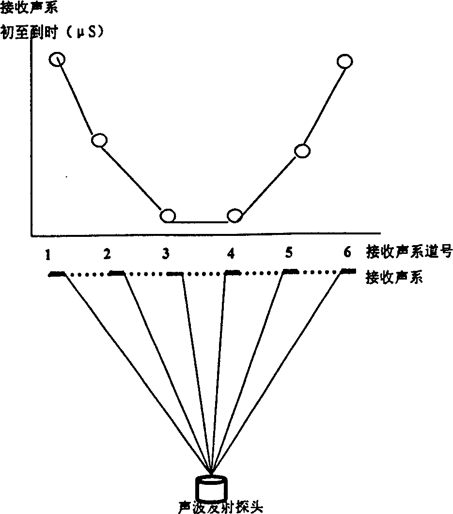
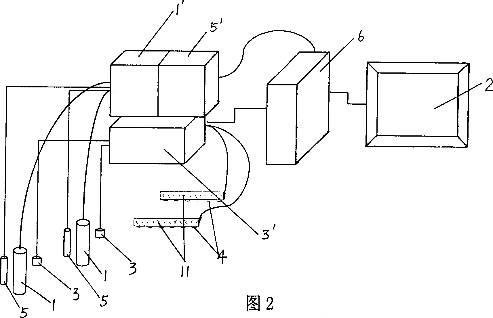
[0041] a. From the ship, sink the underwater detection device connected to the steel cable and composed of underwater TV probe, underwater sound wave transmitter and water depth probe from the approximate water area of ​​the desired positioning target to the bottom of the water, and make the detection device Each probe is connected to the corresponding controller installed on the ship and the control receiving system mainly composed of computers, and the movement of the detection device is controlled by moving the position of the ship and / or steel cable until the underwater TV probe is installed on the ship. The controller connected with the underwater TV probe and the compute...


PUM


Abstract

A method for positioning target under water automatically includes using wirerope on the ship to sink detection device down to water bottom at water area of target to be positioned and confirming its position through image; arranging sound wave receiversin linear array of intervals on water surface, launching sound wave to wards water surface by emitter; sending sound wave signal to computer for calculating out time difference, water depth and target water surface projection position value displayed in curve.

Description

technical field [0001] The invention relates to an automatic positioning method for underwater targets, in particular to a method suitable for dynamic positioning of underwater targets in muddy water, high-velocity water bodies, and turbulent flow water bodies, and real-time projection of underwater targets on the water surface. The following automatic target positioning method and system thereof. Background technique [0002] Underwater positioning is widely used in national defense, water conservancy construction, hydraulic engineering, salvage and other fields. The commonly used methods are positioning through sonar systems and underwater TV equipment. However, when locating objects in water in large rivers such as the Yangtze River and the Yellow River, where the flow velocity is high, the water body is turbid, and the flow state is turbulent, the actual position measured cannot be accurately positioned due to the influence of the current, especially when it is on the wa...

Claims


Application Information

Patent Timeline
Patent Type & Authority Applications(China)
IPC IPC(8): G01B11/03G01S5/18H04N5/225
Inventor 李涛章刘雨泉吴永新廖小元陈云武王建龙
Owner 南京市长江河道管理处
Why Eureka
Try Eureka