Battery clamping

A battery clamp and electrode technology, applied in the direction of clamping/spring connection, etc., can solve the problems of high labor intensity, poor contact, low efficiency, etc., and achieve the effect of reducing labor intensity, improving reliability, and good electrical contact performance

Inactive Publication Date: 2005-05-11
田欣
View PDF0 Cites 7 Cited by
  • Summary
  • Abstract
  • Description
  • Claims
  • Application Information

AI Technical Summary

Problems solved by technology

The above clamps use springs as current conductors, which can easily lead to poor contact, time-consuming, laborious, low efficiency, and labor-intensive

Method used


Image

  • Battery clamping

Examples


Embodiment Construction

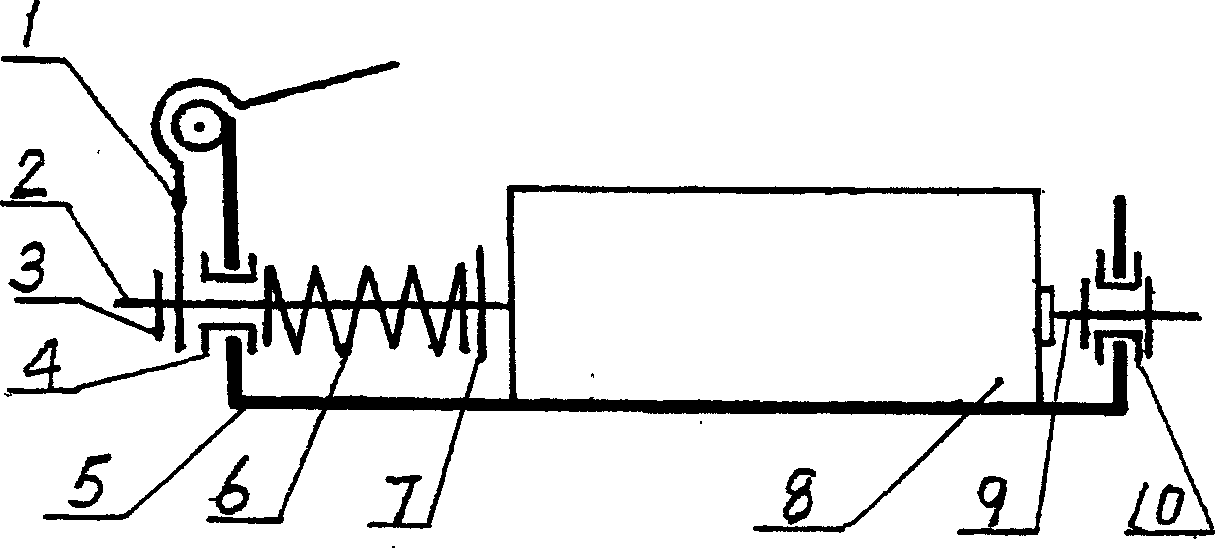
[0012] The battery clamp of the present invention will be further described below with reference to the drawings and embodiments.

[0013] In the figure, the battery clamp consists of a lever 1, a second conductor electrode 2, a second thrust member 3, a guide sleeve 4, a seat body 5, a spring 6, a first thrust member 7, a battery 8, a first conductor electrode 9 and insulator 10.

[0014] The base body 5 is respectively provided with a first conductor electrode 9 and a second conductor electrode 2 for clamping two electrodes of the battery 8 . The first conductor electrode 9 and the second conductor electrode 2 are preferably copper pillars. The second conductor electrode 2 passes through the spring 6 and the guide sleeve 4 installed in the seat. The inner end of the second electrode conductor is provided with a first thrust piece 7, and the spring 6 is limited by the first thrust piece 7 and the guide sleeve 4. Between; the outer end is provided with a second thrust member...


PUM


Abstract

The invention consists of electrode, spring and battery holder composed of base. The first conduction electrode is set on side plate located on one side of the base. The insulator is set between the above first conduction electrode and the base. The lever and second conduction electrode are set on the side plate located at other side of base.

Description

technical field [0001] The invention relates to a clamp, in particular to a clamp for batteries. Background technique [0002] The battery must be placed in a jig in various devices that use the battery, and when the performance of the battery is tested and sorted during the battery production process. A traditional battery clamp is composed of a spring, a seat and an insulator. Using this clamp, the operator can only manually load and unload batteries one by one. The above-mentioned clamp uses springs as current conductors, which is easy to cause poor contact, and is time-consuming, laborious, inefficient, and labor-intensive. Contents of the invention [0003] The purpose of the present invention is to overcome the deficiencies in the prior art and provide a battery fixture with good electrical contact performance and high reliability, which is convenient for loading and unloading batteries, saves time...

Claims


Application Information

Patent Timeline
Patent Type & Authority Applications(China)
IPC IPC(8): H01R4/48
Inventor 田欣
Owner 田欣
Why Eureka
Try Eureka