Aerosol powder valve

A technology for aerosols and aerosol containers, applied in the field of valves for dispensing products, can solve problems such as non-level sealing surfaces, achieve the effect of eliminating powder accumulation and maintaining continuous circulation

Inactive Publication Date: 2005-05-11
PRECISION VALVE CORP
View PDF5 Cites 6 Cited by
  • Summary
  • Abstract
  • Description
  • Claims
  • Application Information

AI Technical Summary

Problems solved by technology

In the patented design, there are no horizontal sealing surfaces and no common grooved surfaces

Method used


Image

  • Aerosol powder valve
  • Aerosol powder valve
  • Aerosol powder valve

Examples


Embodiment Construction

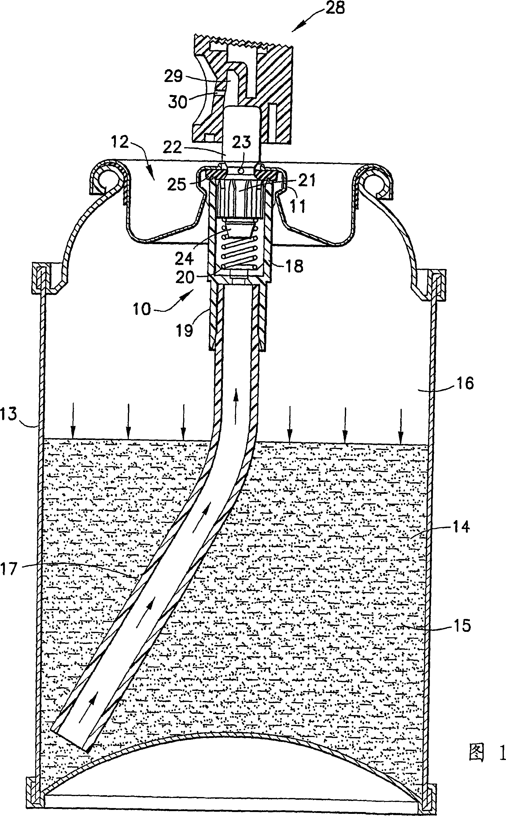
[0023] Referring to FIGS. 1-4 , an aerosol valve assembly, indicated generally at 10 , is mounted and crimped to a base portion 11 of a pressurized container 13 where a cup closure 12 is mounted. The container 13 contains a liquid propellant 14, in which is suspended a powder product 15, and a gas-phase propellant 16 above the liquid propellant.

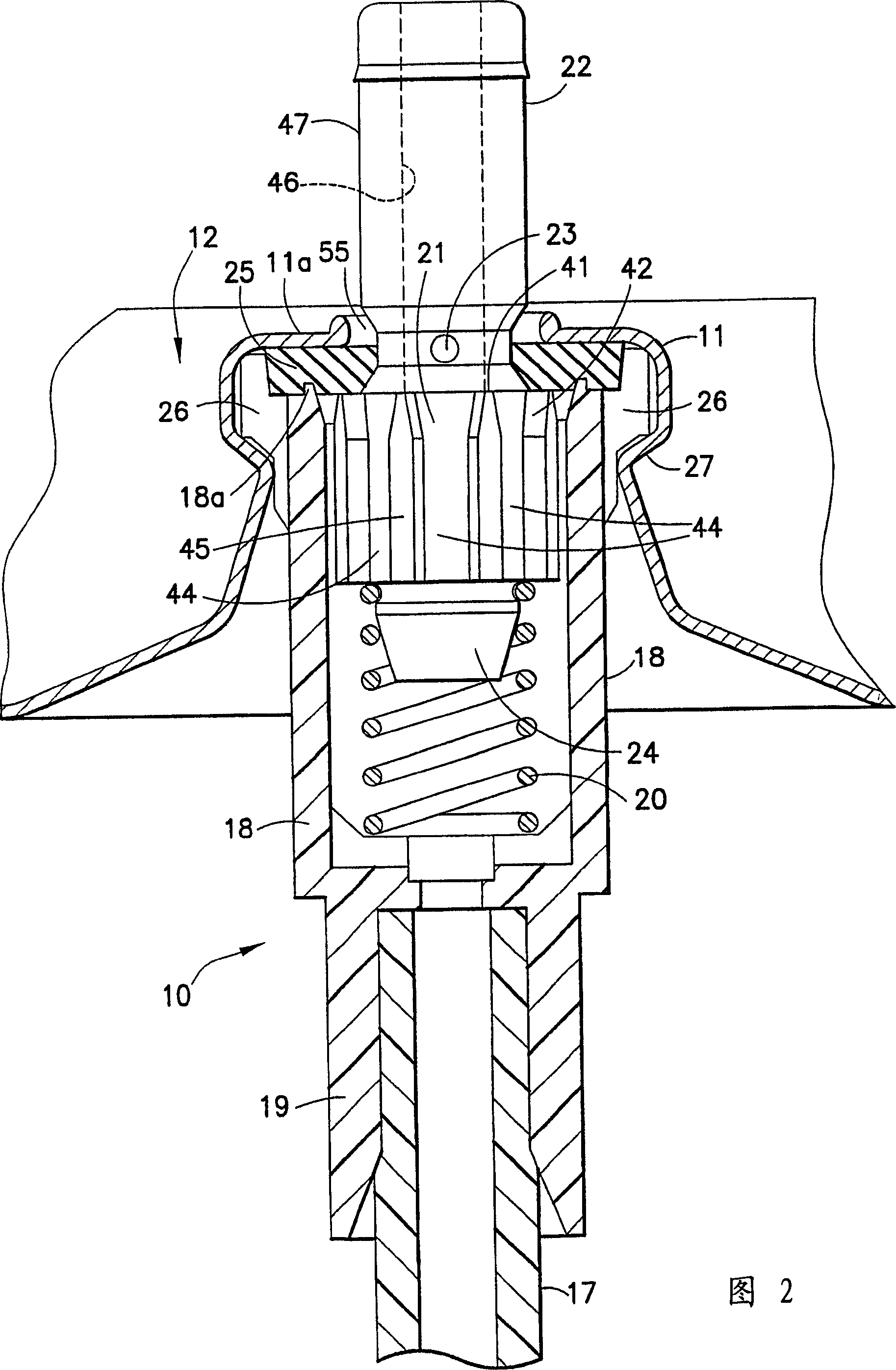
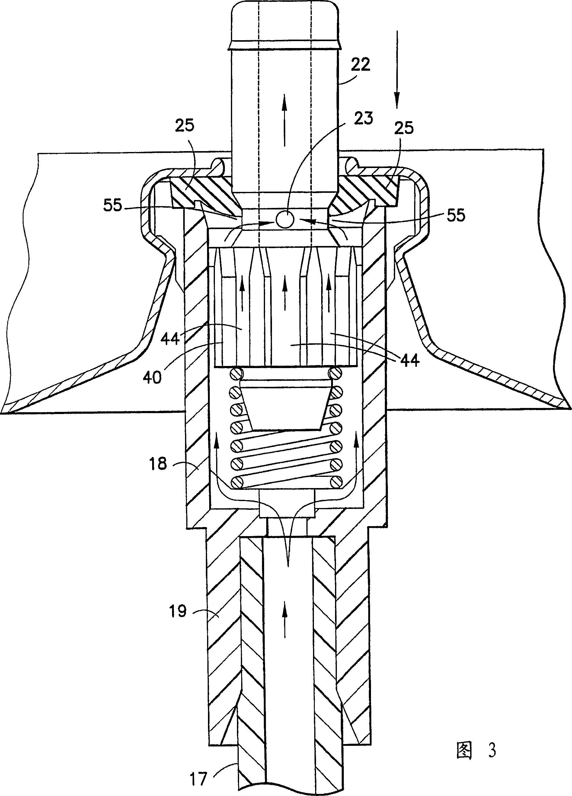
[0024] Valve assembly 10 generally includes a dip tube 17 , a valve housing 18 , a dip tube receiving passage 19 at the bottom of valve housing 18 , valve closing coil spring 20 , and valve body 21 . The valve body 21 has a hollow valve stem 22 extending upwardly from the valve body 21 and including two transverse holes 23 which enter the interior of the valve stem 22 from the valve stem groove 55 . The protrusion 24 extends downward from the valve body 21 and occupies and centers the top of the coil spring 20 .

[0025]A resilient annular gasket 25 surrounds the valve stem 22, extends into an annular groove 55 of the valve stem 22,...


PUM


Abstract

An aerosol powder valve (10) having a valve body (21) under a groove (55) with a plurality of vertical splines (40) having a top surface of minimum area (41), against the washer (25) in the closed position. The groove (55) has an upper annular surface (56), a central neck (57) with the valve hole (23) and a lower annular surface (58) extending downward from the neck at an acute angle relative to the horizontal and extend outwards to the valve body (21), connecting the outer peripheral surface of the valve body at the height of the top of the spline. The acute-angled annular lower groove surface (58) is frusto-conical or convex and has no horizontal or concave portions for powder accumulation. The gasket seals against the lower surface of the groove in the valve closed position and, as the valve moves from the open position to the closed position, sweeps the lower surface of the groove outward so that powder on the groove falls into the circumferential spaces between the splines middle.

Description

technical field [0001] The present invention relates to valves for dispensing products from pressurized containers, in particular to aerosol valves (Aerosol valves) for dispensing powders held in such containers suspended in a liquefied propellant. Background technique [0002] In the traditional form of aerosol valve assembly, a vertically acting aerosol valve is opened by pressing down on a button or cap mounted on top of the upright stem of the aerosol valve to release the product in the container. When the button is released, the valve is closed by the spring acting on the valve. The valve body located below the valve stem has an upper horizontal continuous sealing surface circumferentially surrounding the valve stem. When the aerosol valve is closed, this upper horizontal surface is forced upwardly into sealing relationship with the valve sealing gasket by a spring acting on the valve body. One or more holes in the valve stem are above the lower surface of the valve ...

Claims


Application Information

Patent Timeline
IPC IPC(8): B65D83/44B05B9/04B65D83/14B65D83/16
CPCB65D83/48B65D83/16B65D83/28
Inventor 克里斯琴·拜尔
Owner PRECISION VALVE CORP
Why Eureka
Try Eureka