Wheel bearing with improved cage

A cage and wheel technology, applied in the direction of rotating bearings, bearings, wheels, etc., can solve problems such as the inability to ensure the positional accuracy of seals

Inactive Publication Date: 2005-05-18
THE TIMKEN CO
View PDF0 Cites 2 Cited by
  • Summary
  • Abstract
  • Description
  • Claims
  • Application Information

AI Technical Summary

Problems solved by technology

The accuracy of the seal position cannot be ensured in the design of the tool

Method used


Image

  • Wheel bearing with improved cage
  • Wheel bearing with improved cage
  • Wheel bearing with improved cage

Examples


Embodiment Construction

[0023] The following detailed description will illustrate the present invention by way of example, rather than limit the present invention. This description will clearly enable one skilled in the art to make and use the invention, and will explain what we presently believe to be the best mode of carrying out the invention.

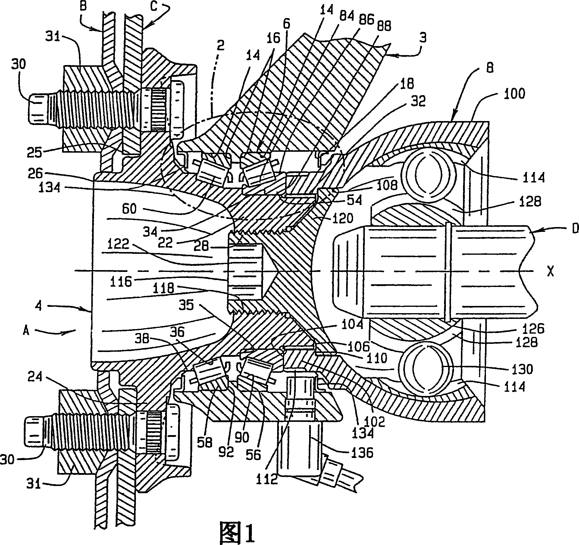
[0024] Referring now to FIG. 1 , a hub assembly A connects a wheel B and brake rotor C of a motor vehicle to the vehicle's suspension system and may further connect wheel B to a drive shaft D forming part of the vehicle's driveline. The suspension system includes (FIG. 1) a suspension member 3 designed to move generally perpendicular to the vehicle, preventing deflection of the springs or torsion bars. When the wheel B connected to the hub assembly A is at the front of the vehicle so that the vehicle can be steered, the suspension member 3 generally takes the form of a steering knuckle. On the other hand, when the wheel B is located at the rear of the veh...


PUM


Abstract

For example, an improved cage (60, 362, 363) is provided for a roller bearing (60, 360) used in a hub assembly (A). The cage (60, 362, 363) includes a roller sleeve (70) that fully encloses the rollers (60, 360) in the cage to maintain the radial and axial orientation of the rollers (60, 360) in the cage Location. In addition, the bearing (6) part of the hub assembly (A) is formed by the hub. One of the inner races (36) is integral with the hub (4). These configurations allow the cage / roller assembly to be installed in an outboard location of the hub (4) before the hub (4) and hub seal (134) are installed in the hub assembly (A).

Description

technical field [0001] This invention relates generally to wheel hub assemblies for motor vehicles and, in particular, to a new and improved cage for bearings in the wheel hub assembly which facilitates assembly of the wheel hub assembly. Background technique [0002] The wheels of many motor vehicles currently manufactured are connected to their suspension systems by hub assemblies provided as packaged units ready for installation during the assembly of these vehicles. A typical hub assembly consists primarily of a housing of some type that is placed over a component of the vehicle's suspension system; a hub to which the wheel and brake rotor are secured; and a housing between the hub and the housing. Bearings that allow the hub to rotate relative to the housing with minimal friction. The bearings must accommodate thrust and radial loads and are preferably set to a preloaded condition so that the bearings run without internal clearance; as a result the rotating shaft remai...

Claims


Application Information

Patent Timeline
Patent Type & Authority Applications(China)
IPC IPC(8): F16C33/46B29C67/00B60B27/00B60S1/38F16C19/36F16C19/38F16C33/48F16C33/49F16C33/58
CPCF16C19/386F16C33/4635F16C33/4682F16C33/485F16C2326/02
Inventor M·A·约基T·J·雷布科夫斯基
Owner THE TIMKEN CO
Why Eureka
Try Eureka