Voice enhancement system

A noise and non-noise technology, applied in the field of sound enhancement system, can solve problems such as sound signal distortion and operating power waste

Inactive Publication Date: 2005-05-25
CLEAR AUDIO
View PDF7 Cites 16 Cited by
  • Summary
  • Abstract
  • Description
  • Claims
  • Application Information

AI Technical Summary

Problems solved by technology

In this embodiment, the audible signal is distorted due to different independent amplifications of different frequency components of the signal
Also

Method used


Image

  • Voice enhancement system
  • Voice enhancement system
  • Voice enhancement system

Examples


Embodiment Construction

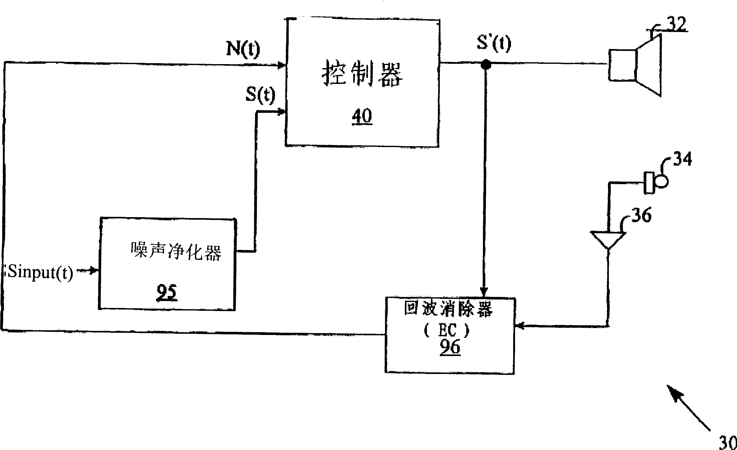
[0056] figure 1 It is a schematic diagram of a noise compensation system 30 according to an embodiment of the present invention. The system 30 receives the input sound signal Sinput(t) emitted by the speaker 32. For example, receiving Sinput(t) from a remote party in a telephone conversation. The controller 40 receives the input sound signal Sinput(t) and the estimated value N(t) of noise near the speaker 32, and provides a noise compensation input signal S'(t), which is a noise compensation form of the input sound signal Sinput(t).

[0057] In some embodiments of the present invention, the input sound signal Sinput(t) will pass through the noise cleaner 95, which is responsible for providing the noise filtering form S(t) of the input sound signal Sinput(t). The operation of the noise cleaner 95 is independent of the noise level near the speaker 32. When there is no voice signal, the noise purifier 95 can measure the noise according to the situation and determine the frequency s...


PUM


Abstract

A method of processing an audio signal with the aim of overcoming the effects of background noise unrelated to the audio signal. The method includes comparing a measure of the audio signal in frequency components of the audio signal with a measure of noise in the frequency components of background noise, determining a gain factor based on the comparison and using the determined gain factor to amplify at least a portion of the audio signal, including at least one Frequency bins in the frequency components of a signal.

Description

[0001] Related applications [0002] This patent application claims the priority of the provisional application No. 60 / 224,513 filed on August 14, 2000 and the provisional application No. 60 / 236,721 filed on October 2, 2000, based on the US Patent Law (35 USC) 119 According to Article 5, the disclosed content is incorporated into this article by reference. In addition, this patent application is a partial continuation application (CIP) of the PCT (Patent Cooperation Treaty) application PCT / US00 / 20395 filed on July 27, 2000, and the disclosed content is incorporated herein by reference. Technical field [0003] The present invention relates to a sound enhancement system. Background technique [0004] Telephones are usually used in noisy environments, where background noise can interfere with the understanding of sound signals received by the telephone. [0005] Goldberg's US Patent No. 4,829,565, the disclosure of which is incorporated herein by reference, describes a telephone wit...

Claims


Application Information

Patent Timeline
IPC IPC(8): G10L21/02G10L15/20H03GH03G3/32H03G9/02H03G9/14H04R3/00
CPCH03G3/32H03G9/005H03G9/025H04R3/00G10L21/02
Inventor Z·利希特
Owner CLEAR AUDIO
Why Eureka
Try Eureka