Master and auxiliary combustion device

A technology of main burner and auxiliary burner, which is applied in the direction of burner, gas fuel burner, and the combination of multiple burners, can solve the problems of reduction of gas volume, deterioration of flame flammability, and narrow flame hole of incision, etc. Achieve the effect of increasing the amount of gas and improving the flame flammability

Active Publication Date: 2005-06-01
RINNAI CORP
View PDF1 Cites 2 Cited by
  • Summary
  • Abstract
  • Description
  • Claims
  • Application Information

AI Technical Summary

Problems solved by technology

[0004] However, if the outer peripheral portion of the main burner top hat is completely divided in this way, the incision flame hole becomes narrow radially outward due to the thermal expansion of the main burner top hat, and jets from the incision flame hole The amount of gas output is reduced, resulting in poor flame spread between the flame hole of the main burner and the flame hole of the auxiliary burner
In particular, when the main burner top hat is formed of a material whose thermal expansion rate is larger than that of the burner head on which it is placed, the thermal expansion of the main burner top hat is determined by the embedding of the inner peripheral side of the main burner head. In the case where the entire top cap of the main burner cannot perform equal thermal expansion due to the restriction of the joint, the notch flame hole will become the escape part of the thermal expansion of the top cap of the main burner, so the notch flame hole will easily become narrow, resulting in Deterioration of flame spread

Method used


Image

  • Master and auxiliary combustion device
  • Master and auxiliary combustion device
  • Master and auxiliary combustion device

Examples


Embodiment Construction

[0020] Hereinafter, embodiments of the present invention will be described with reference to the drawings.

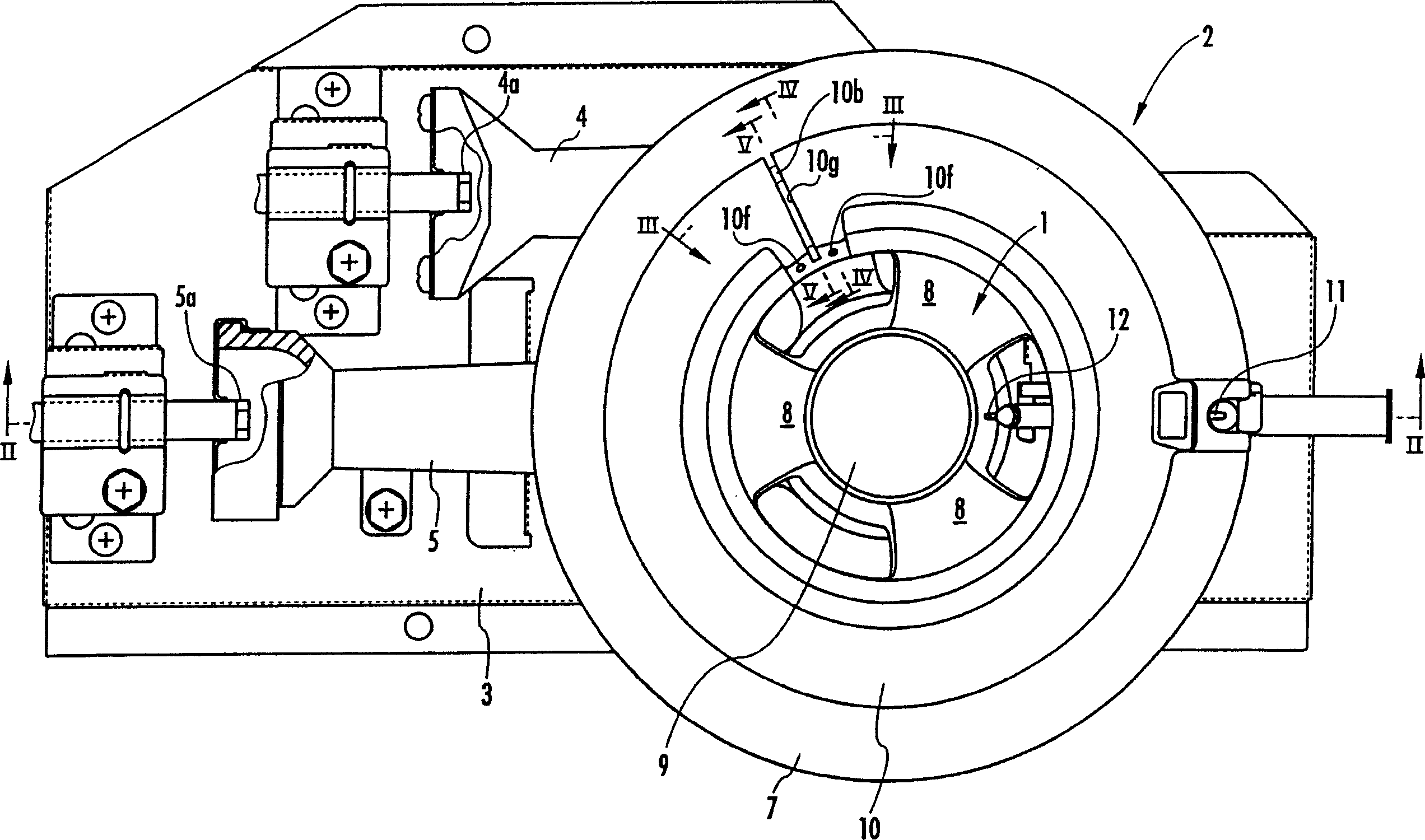
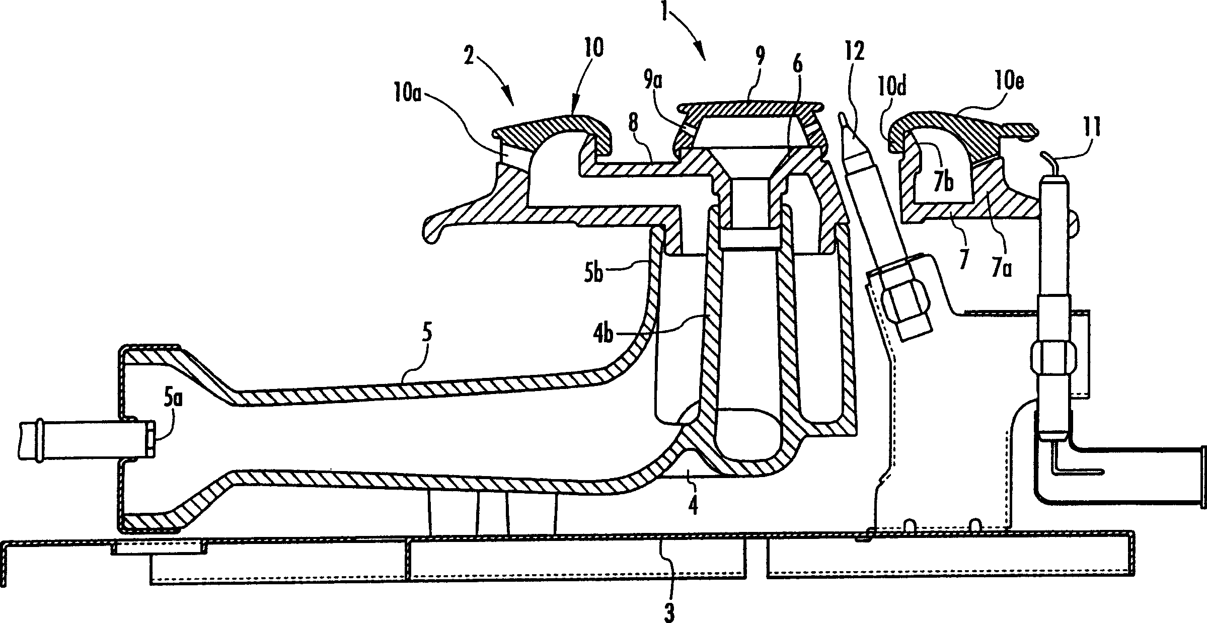
[0021] figure 1 , figure 2 The shown burner is a main and auxiliary burner composed of an auxiliary burner 1 and a main burner 2 surrounding the auxiliary burner 1, and the main and auxiliary burners are fixedly placed on a furnace base 3 inside a furnace body (not shown). superior. The main and auxiliary burners have an auxiliary burner mixing tube 4 and a main burner mixing tube 5 . And make each gas nozzle 4a, 5a face the upstream end of respective mixing pipe 4, 5, to generate in each mixing pipe 4, 5 the gas ejected from each gas nozzle 4a, 5a and the ejection of accompanying gas for suction Comes once the air is mixed with the mixture. Both mixing pipes 4, 5 are integrally formed at the downstream side thereof, and are integrally cast from cast iron. The integral part of the two mixing tubes 4 and 5 is formed by an inner tube 4b opening above the downstream ...


PUM


Abstract

The present invention provides a master-and-slave combined burner, wherein a slit burner port is provided in an upper wall of a master burner cap and extends in a radial direction to allow fire to spread between a master burner port and a slave burner port and to prevent narrowing of the slit burner port caused by thermal expansion of the master burner cap, and also preventing deterioration of fire spreading performance. Further, the slit burner port is formed so as to reach an outer circumferential rim of the master burner cap through an upper portion of any bulkhead portions positioned between master burner ports of an outer circumferential side peripheral wall part of the master burner cap. The bulkheads act as supports to suppress narrowing of the slit burner port caused by thermal expansion of the master burner cap.

Description

technical field [0001] The invention relates to a main and auxiliary burner mainly used on a gas stove. Background technique [0002] In the past, as such a main and auxiliary burner, it is well known to have an auxiliary burner top cap and an annular main burner top cap surrounding the auxiliary burner top cap, and to have A plurality of sub burner flame holes are formed at intervals, and a plurality of main burner flame holes are formed at intervals in the circumferential direction on the peripheral wall portion on the outer peripheral side of the main burner top cap. In addition, such main and auxiliary burners are generally in the form of igniting one of the main burner and the auxiliary burner by an igniter, and then spreading the flame (extended combustion) to the flame hole of the other. [0003] Thus, the upper wall of the top cap of the main burner is provided with a notch flame hole extending in the radial direction for the flame spread between the flame hole of t...

Claims


Application Information

Patent Timeline
Patent Type & Authority Applications(China)
IPC IPC(8): F23D14/06F23D23/00
CPCF23D14/06F23D14/48F23D14/76F24C3/027F24C3/085
Inventor 佐藤裕康
Owner RINNAI CORP
Why Eureka
Try Eureka