Lubricating oil tank oil suction and exhaust mechanism capable of adapting to multiple working postures of airplane

A technology of exhaust mechanism and lubricating oil tank, which is applied in the direction of engine lubrication, turbine/propulsion lubrication, engine components, etc. Reduced ventilation resistance, stable ventilation efficiency, and reduced number of parts

Pending Publication Date: 2022-07-29
AECC SHENYANG ENGINE RES INST
View PDF0 Cites 0 Cited by
  • Summary
  • Abstract
  • Description
  • Claims
  • Application Information

AI Technical Summary

Problems solved by technology

[0004] However, this structural form can only meet the requirements for the use of oil tanks with relatively thin outer dimensions and relatively simple internal structures. However, as the structure of the oil tank becomes more and more complex and there are more and more welding parts, it often occurs Phenomenon that the exhaust efficiency is not high, and the oil-absorbing ball head is stuck and cannot work normally

Method used


Image

  • Lubricating oil tank oil suction and exhaust mechanism capable of adapting to multiple working postures of airplane
  • Lubricating oil tank oil suction and exhaust mechanism capable of adapting to multiple working postures of airplane
  • Lubricating oil tank oil suction and exhaust mechanism capable of adapting to multiple working postures of airplane

Examples


Embodiment Construction

[0041] In order to make the implementation purpose, technical solutions and advantages of the present application clearer, the technical solutions in the embodiments of the present application will be described in more detail below with reference to the accompanying drawings in the embodiments of the present application.

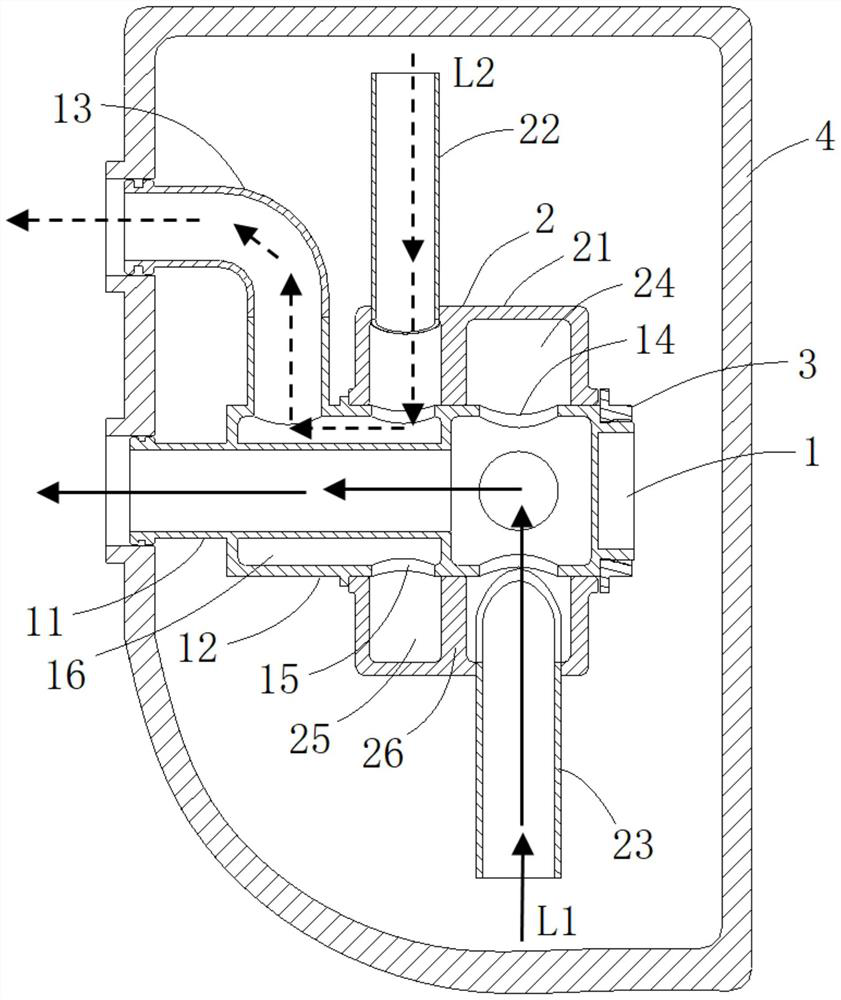
[0042] In order to realize the normal fuel supply and exhaust of the aircraft under various flight attitudes, and at the same time to improve the reliability and maintainability of the oil suction and exhaust device, the oil supply and exhaust device can be set up smoothly when the internal space of the oil tank is limited. , the present application provides an oil suction and exhaust device for a lubricating oil tank that can adapt to multiple working attitudes of an aircraft.

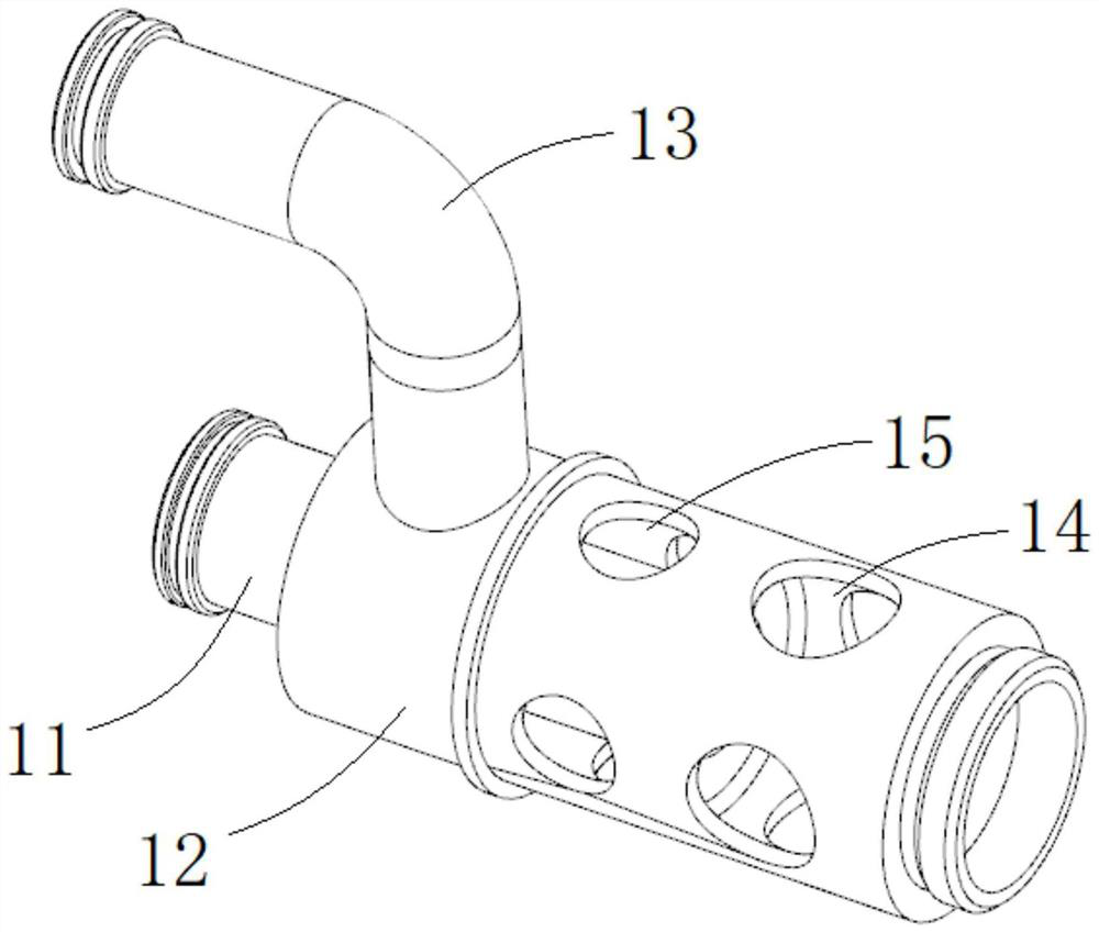
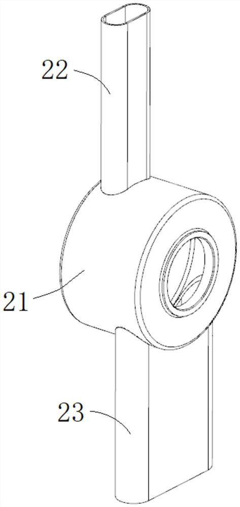
[0043] like figure 1 As shown, the oil suction and exhaust device provided by the present application includes a fixed shaft 1 , a rotating mechanism 2 and a limit nut 3 .

[0044]...


PUM


Abstract

The invention provides a lubricating oil tank oil suction and exhaust mechanism capable of adapting to multiple working postures of an airplane, comprising: a fixed shaft comprising a hollow shaft, an outer sleeve and an exhaust pipe, a plurality of circumferentially distributed oil suction holes on the hollow shaft, the oil suction holes communicating with the middle part of the hollow shaft, the outer sleeve is fixed on the outer side of the hollow shaft, the outer sleeve and the hollow shaft form a hollow interlayer which is not communicated with the middle part, a plurality of exhaust holes are also formed in the circumferential direction of the outer sleeve, and the exhaust pipe is installed on the outer sleeve and communicated with the exhaust holes; the rotating mechanism comprises an annular body, an exhaust pipe and an oil suction pipe, the annular body is provided with an annular cavity and is divided into an oil suction cavity and an exhaust cavity which are not communicated with each other by a partition, a through hole for connecting the oil suction cavity and the exhaust cavity is formed in the outer wall of the annular body, the exhaust pipe and the oil suction pipe are respectively connected to the through hole, and the rotating mechanism is rotatably mounted on the fixed shaft; the oil suction cavity covers the oil suction hole, and the exhaust cavity covers the exhaust hole; and the positioning nut is mounted on the fixed shaft and is used for limiting the rotating mechanism on the fixed shaft.

Description

technical field [0001] The application belongs to the technical field of aviation gas turbine engines, and in particular relates to a lubricating oil tank oil suction and exhaust mechanism capable of adapting to multiple working attitudes of an aircraft. Background technique [0002] Aviation gas turbine engine lubricating oil tank is an important device for storing, supplying and collecting lubricating oil. During the operation of the aviation gas turbine engine, a large amount of air is attached to the lubricating oil tank in the collected lubricating oil, so an exhaust port is usually arranged in the lubricating oil tank to discharge the excess air out of the lubricating oil tank. Due to the combined action of gravity and flight acceleration, the oil is always in the lower part of the fuel tank or on the tangent plane of the flight acceleration, while the air is always in the upper part. If the fuel supply port and exhaust port are fixed, when the flight attitude of the ...

Claims


Application Information

Patent Timeline
Patent Type & Authority Applications(China)
IPC IPC(8): F02C7/06
CPCF02C7/06
Inventor 胡兴龙左斌辉
Owner AECC SHENYANG ENGINE RES INST
Why Eureka
Try Eureka