engine air intake

A technology for air intake devices and engines, applied in the direction of engine components, machines/engines, charging systems, etc., can solve the problem of not being able to distribute air, not sufficiently reducing the ventilation resistance of the intake device, and not considering the reduction of the ventilation resistance of branch pipes Equalization of air intake distribution and other issues to achieve the effects of improving output performance, reducing bending, and reducing ventilation resistance

Active Publication Date: 2018-10-19
SUZUKI MOTOR CORP
View PDF7 Cites 0 Cited by
  • Summary
  • Abstract
  • Description
  • Claims
  • Application Information

AI Technical Summary

Problems solved by technology

[0011] However, the device described in Patent Document 1 does not take into account the reduction of the ventilation resistance of all the branch pipes and the equalization of the intake air distribution amount, so there is a problem that the ventilation resistance of the entire intake device cannot be sufficiently reduced, and it cannot be adjusted for each branch pipe. Branch pipes distribute air equally

Method used


Image

  • engine air intake
  • engine air intake
  • engine air intake

Examples


Embodiment Construction

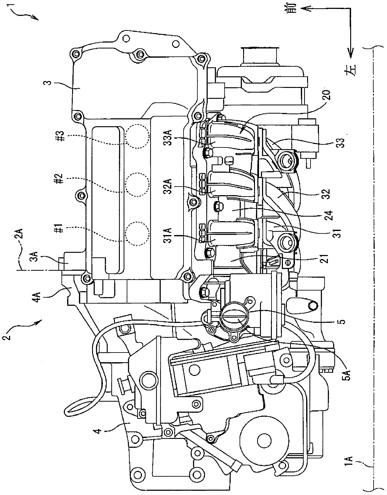
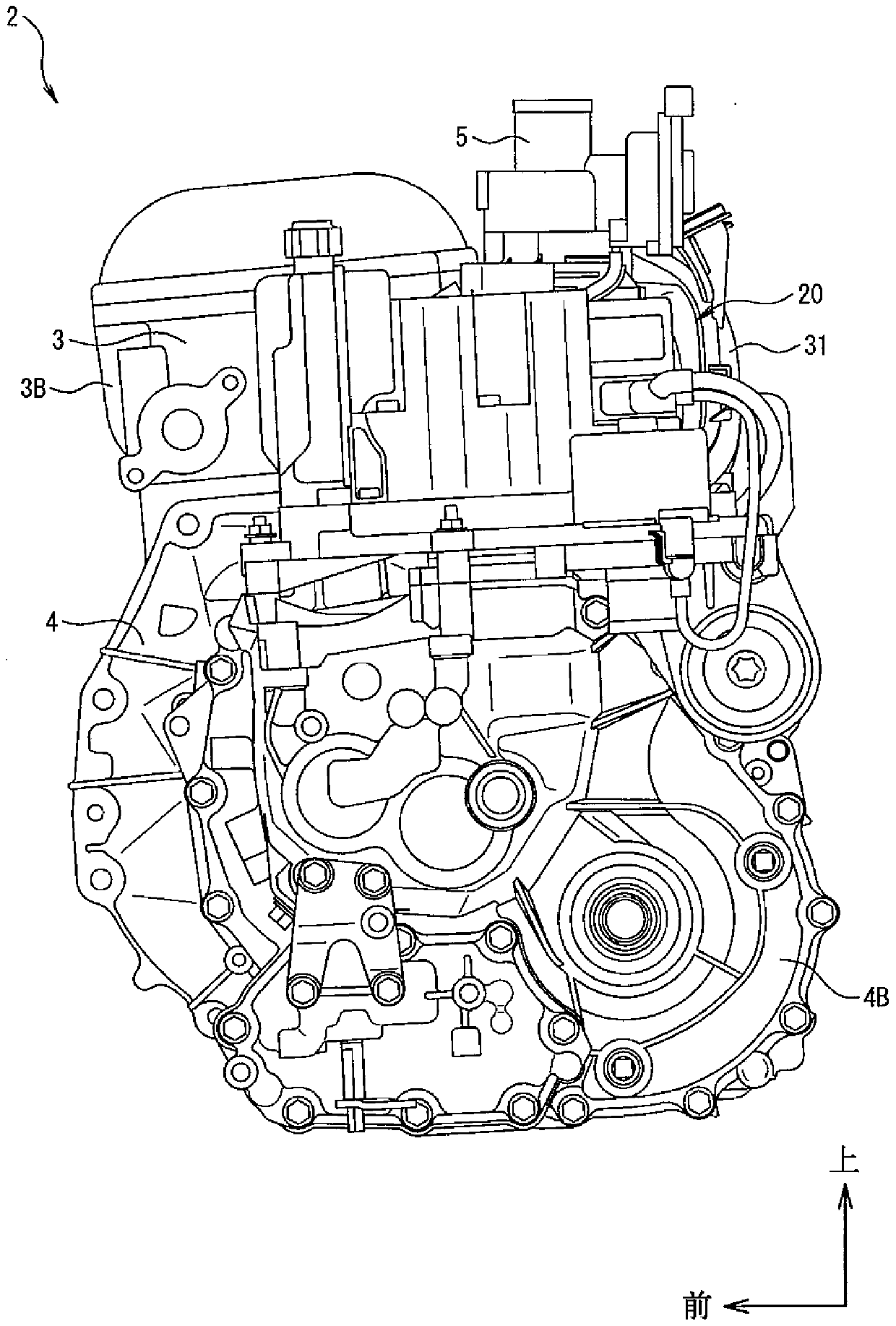
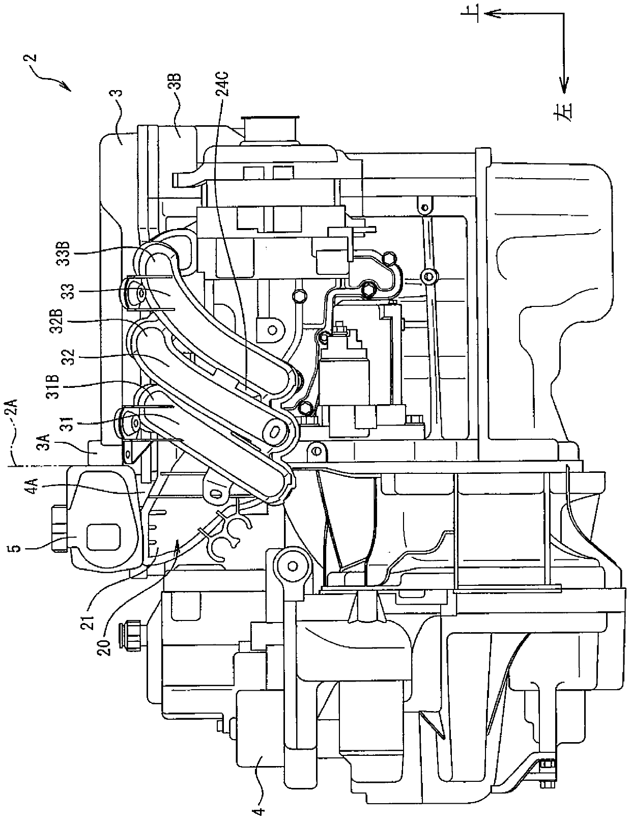
[0032] Embodiments of an air intake device for an engine according to the present invention will be described below using the drawings. Figure 1 to Figure 9 It is a figure which shows the air intake device of the engine which concerns on one Embodiment of this invention.

[0033] First, the configuration will be described. exist figure 1 In the vehicle 1, a power system 2 is installed on the vehicle 1, and the power system 2 is installed laterally in front of the instrument panel 1A of the vehicle 1. The instrument panel 1A is provided in front of an unillustrated driver's seat, and separates a space in which the powertrain 2 is arranged from the driver's seat.

[0034] In the present embodiment, the front-rear, left-right, and up-down directions are indicated by arrows in the figure so as to correspond to the front-rear direction, left-right direction, and up-down direction viewed by the driver sitting on the driver's seat of the vehicle 1 .

[0035] The power system 2 i...


PUM


Abstract

An intake device for an engine can reduce the ventilation resistance of intake air and distribute air into a plurality of branch pipes equally, and the output performance of the engine can be improved. The plurality of branch pipes (31, 32, 33) extends from the downstream end portions in the intake air flow direction toward the upstream end portions (31A, 32A, 33A) in the intake air flow direction, and the plurality of branch pipes are close to an intake air induction pipe (21) and are spiral in the column direction of air cylinders. The intake air induction pipe (21) is provided with a channel portion (22) which is connected with the upper surface of a buffer tank (24) from the inclined upward side of the buffer tank (24). The upper surface (22A) of the channel portion (22) is inclined to make a first imaginary plane (V1) extend to the upstream end portion (33A) in the intake air flow direction of the branch pipe (33) arranged on the other end portion in the arraying direction of the plurality of branch pipes (31, 32, 33).

Description

technical field [0001] The present invention relates to an intake device for an engine, and more particularly to an intake device for an engine including a branch pipe for supplying air to a plurality of cylinders. Background technique [0002] An engine installed in a vehicle such as an automobile is provided with an air intake device for sending air into a cylinder. Generally, the air intake device of a multi-cylinder engine such as a 3-cylinder engine has a structure in which one intake pipe and a plurality of branch pipes are connected through a buffer tank, and the intake air introduced into the intake pipe passes through the buffer tank and the branch pipes. Change direction. [0003] In the air intake device of such an engine, depending on the shape of the buffer tank and the branch pipe, the advancing direction of the intake air changes rapidly, thereby increasing the ventilation resistance and reducing the output of the engine. [0004] On the other hand, the devi...

Claims


Application Information

Patent Timeline
Patent Type & Authority Patents(China)
IPC IPC(8): F02M35/104
CPCF02M35/10072F02M26/41F02M35/112
Inventor 福岛章
Owner SUZUKI MOTOR CORP
Why Eureka
Try Eureka