Refrigeration cycle apparatus

A technology of circulation device and refrigerant, which is applied in gas cycle refrigerators, irreversible cycle compressors, refrigerators, etc., can solve the problems of reliability decline and pressure rise of refrigeration cycle devices.

Inactive Publication Date: 2005-06-08
PANASONIC CORP
View PDF1 Cites 7 Cited by
  • Summary
  • Abstract
  • Description
  • Claims
  • Application Information

AI Technical Summary

Problems solved by technology

[0009] For this reason, various investigations have been carried out on refrigeration cycle equipment without storage tanks or accumulators. As a result, it has been found that in normal operating conditions, by adjusting the opening of the pressure reducer, the holding capacity of the low-pressure side is equal to that of the high-pressure side. The ratio of the holding volume is changed, so that the pressure on the high-pressure side can be adjusted to some extent, but in the case of the fluid radiated by the radiator (such as indoor air and outside air in the case of an air conditioner, and in the case of a hot water supplier, etc. When the temperature of the high-pressure side is high, there is a problem that the reliability of the refrigeration cycle device will decrease due to an abnormal increase in the pressure of the high-pressure side

Method used


Image

  • Refrigeration cycle apparatus
  • Refrigeration cycle apparatus
  • Refrigeration cycle apparatus

Examples


Embodiment 1

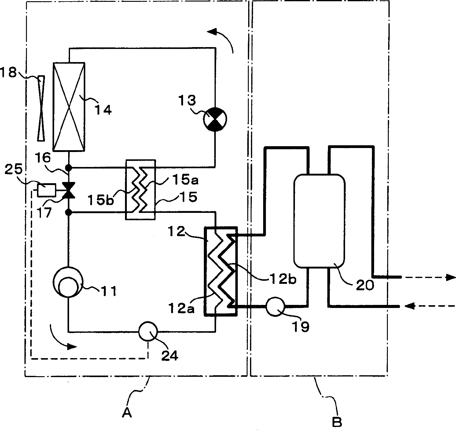
[0035] Hereinafter, a refrigeration cycle apparatus according to an embodiment of the present invention will be described by taking a hot water supplier as an example with reference to the drawings. The present invention is not limited by this embodiment. figure 1 It is a configuration diagram showing the refrigeration cycle apparatus according to the first embodiment of the present invention.

[0036] The refrigeration cycle apparatus of the first embodiment includes a refrigerant circuit A and a fluid circuit B; the refrigerant circuit A includes a compressor 11, a refrigerant flow path 12a of a radiator 12 as a heat exchanger for hot water supply, and an internal heat exchange circuit. The high-pressure side refrigerant flow path 15a of the unit 15, the pressure reducer 13, the evaporator 14, the low-pressure side refrigerant flow path 15b of the internal heat exchange unit 15, etc.; Road 12b, hot water supply tank 20, etc.

[0037]In the above-mentioned refrigerant circ...

Embodiment 2

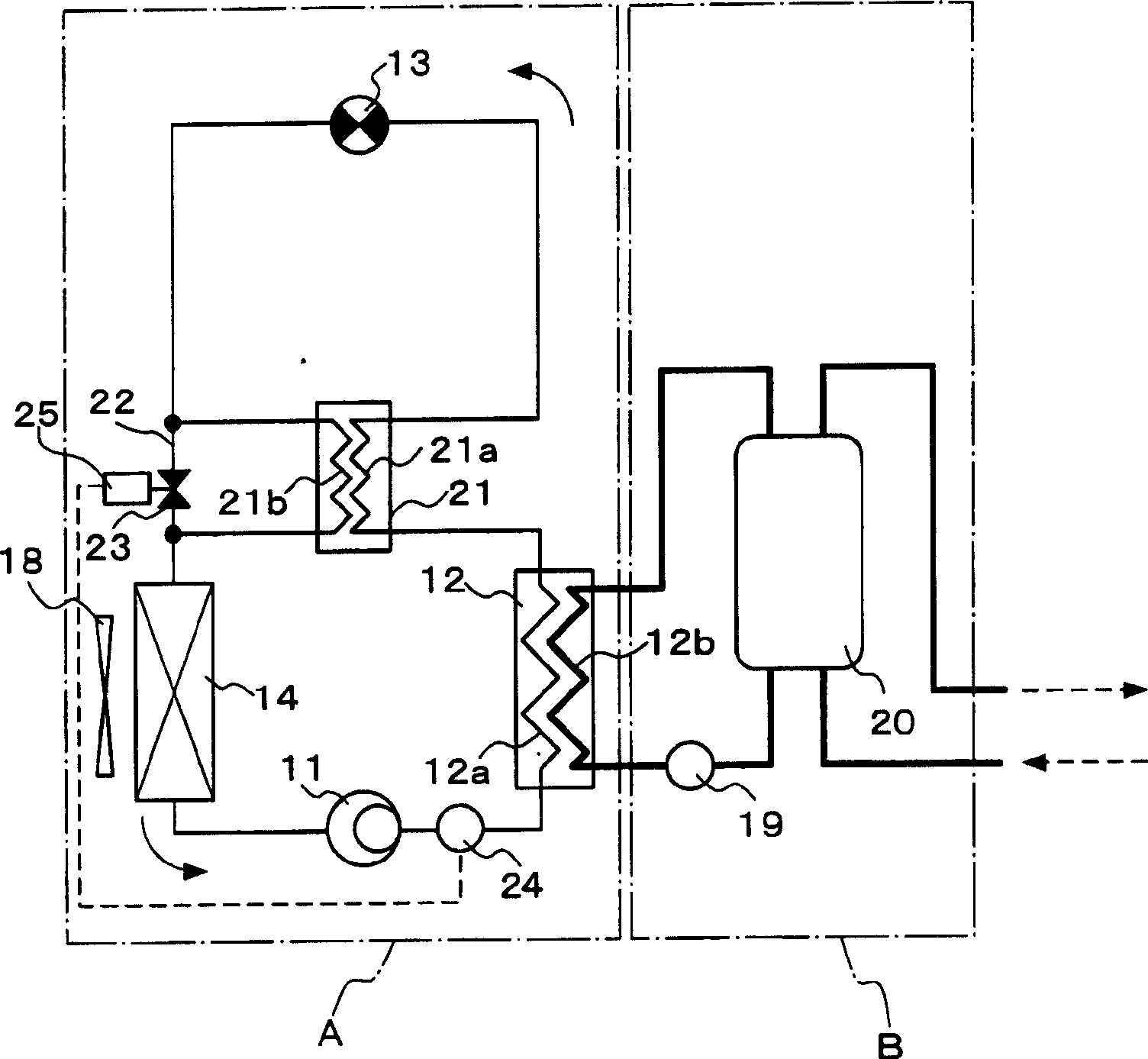
[0047] figure 2 It is a configuration diagram showing a refrigeration cycle apparatus according to a second embodiment of the present invention. In this embodiment, the same constituent elements as in the first embodiment are adopted and figure 1 The same symbols are used and their descriptions are omitted, and the configuration and operation different from those of the first embodiment of this embodiment will be described below.

[0048] In the refrigeration cycle apparatus of the second embodiment, the high-pressure side refrigerant flow path 21a of the internal heat exchange unit 21 is provided between the radiator 12 (refrigerant flow path 12a) outlet and the pressure reducer 13 inlet, and the low-pressure side refrigerant The flow path 21b is provided between the outlet of the decompressor 13 and the inlet of the evaporator 14, and is cooled in the radiator 12 by the low-pressure side refrigerant flowing in the low-pressure side refrigerant flow path 21b between the out...

Embodiment 3

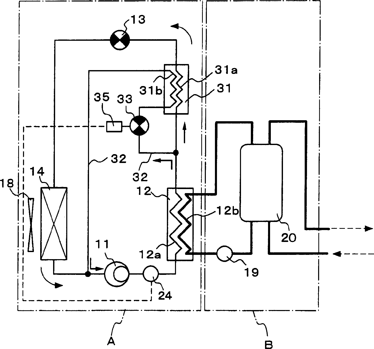
[0055] image 3 It is a configuration diagram showing a refrigeration cycle apparatus according to a third embodiment of the present invention. In this embodiment, the same constituent elements as in the first embodiment are adopted and figure 1 The same symbols are used and their descriptions are omitted, and the configuration and operation different from those of the first embodiment of this embodiment will be described below.

[0056] In the refrigeration cycle apparatus of the third embodiment, the high-pressure side refrigerant flow path 31a of the internal heat exchange unit 31 is provided between the outlet of the radiator 12 (refrigerant flow path 12a) and the inlet of the pressure reducer 13, and the low-pressure side refrigerant flow path The flow path 31b is provided in a bypass circuit 32 that branches between the radiator 12 (refrigerant flow path 12a) and the high-pressure side refrigerant flow path 31a of the internal heat exchange unit 31, and passes through ...


PUM


Abstract

A refrigeration cycle apparatus has a refrigerant circuit A. The refrigerant circuit A comprises a compressor 11, a refrigerant passage 12a of a radiator 12 as a water heating heat exchanger, a high pressure side refrigerant passage 15a of internal heat exchanging means 15, a decompressor 13, an evaporator 14, and a low pressure side refrigerant passage 15b of the internal heat exchanging means 15. In the refrigeration cycle apparatus, a pressure detecting apparatus 24 detects that a high pressure side pressure rises to about design pressure, a first solenoid valve 17 provided in a bypass circuit 16 is controlled, by a solenoid valve control apparatus 25, so as to be closed, a low pressure side refrigerant is allowed to flow into the low pressure side refrigerant passage 15b between an outlet of the evaporator 14 and an inlet of the compressor 11, a high pressure side refrigerant flowing through the high pressure side refrigerant passage 15a between an outlet of the radiator 12 and an inlet of the decompressor 13 is cooled, thereby reducing a high pressure side pressure. <IMAGE>

Description

technical field [0001] The present invention relates to an apparatus as a refrigerant refrigerating cycle using a refrigerant capable of being in a supercritical state on a high-pressure side. Background technique [0002] Conventionally, hydrocarbons containing fluorine atoms (Freons) have been used as refrigerants to be enclosed in refrigeration cycle apparatuses. However, Freon has the property of depleting the ozone layer and has a long lifetime in the atmosphere, so that it has a large greenhouse effect, and therefore affects global warming, so it cannot be said to be a satisfactory refrigerant. Therefore, it has been proposed to use carbon dioxide, ethane, etc. as refrigerants instead of Freon-based refrigeration cycle devices (for example, refer to Patent Document 1). The ozone destruction coefficient of carbon dioxide, ethane, etc. is zero, and the global warming coefficient is comparable to that of Freon. is also very small. [0003] Refrigerants such as carbon di...

Claims


Application Information

Patent Timeline
Patent Type & Authority Applications(China)
IPC IPC(8): F25B1/00F25B9/00F25B40/00
CPCF25B9/008F25B40/00F25B2309/061F25B2339/047F25B2400/13F25B2500/07F25B2600/112F25B2600/17F25B2600/2501F25B2700/1931Y02B30/70
Inventor 冈座典穗
Owner PANASONIC CORP
Why Eureka
Try Eureka