Structure for positioning umbrella stick

A technology for positioning structures and umbrella ribs, applied in the direction of walking sticks, etc., can solve problems such as decoupling and falling of the pivotal hook part 98, quality loss, unstable holding and swinging of umbrellas, etc.

Inactive Publication Date: 2005-06-15
游清泉
View PDF0 Cites 4 Cited by
  • Summary
  • Abstract
  • Description
  • Claims
  • Application Information

AI Technical Summary

Problems solved by technology

[0003] Although the above-mentioned umbrella structure can realize the basic function of connecting the umbrella ribs, when purchasing an umbrella, in order to confirm the structural strength of the umbrella, the general consumer usually pulls it around on the supporting ribs 94 in the ring to test. In this way, the supporting umbrella rib 94 will be subject to a downward pulling force F, that is, the pivot joint 97 will produce a mutual pressing force relative to the pull rod 96, so that the pivot tip 99 of the pivot joint 97 will be separated from the pivot joint 97. The hooking position of the pivotal hook portion 98 supporting the umbrella rib 94 even causes the pivotal hook portion 98 to break away from the hooking of the pivot tip 99 and fall off, resulting in a serious lack of quality (ie defective product).
Furthermor

Method used


Image

  • Structure for positioning umbrella stick
  • Structure for positioning umbrella stick
  • Structure for positioning umbrella stick

Examples


Embodiment Construction

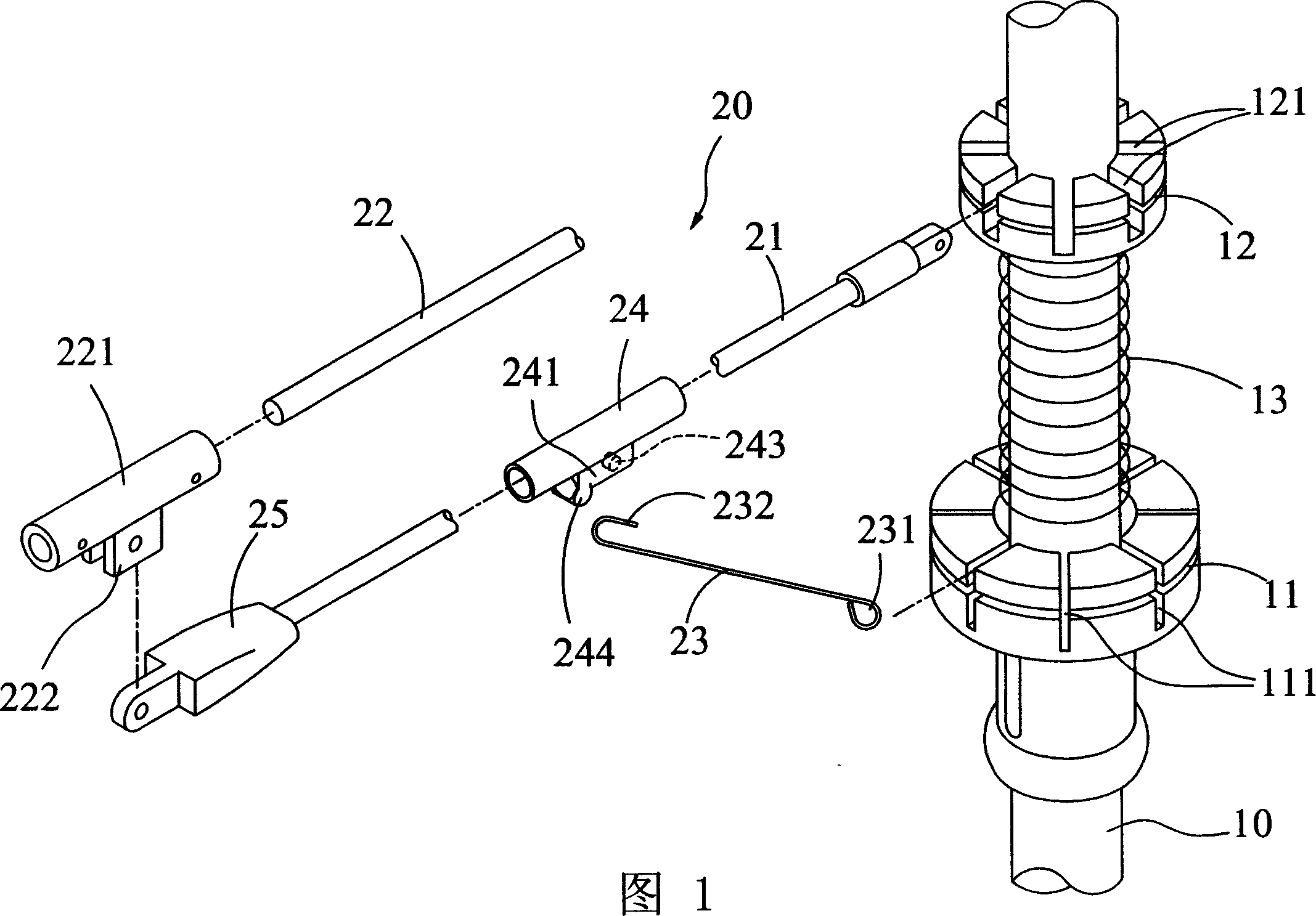
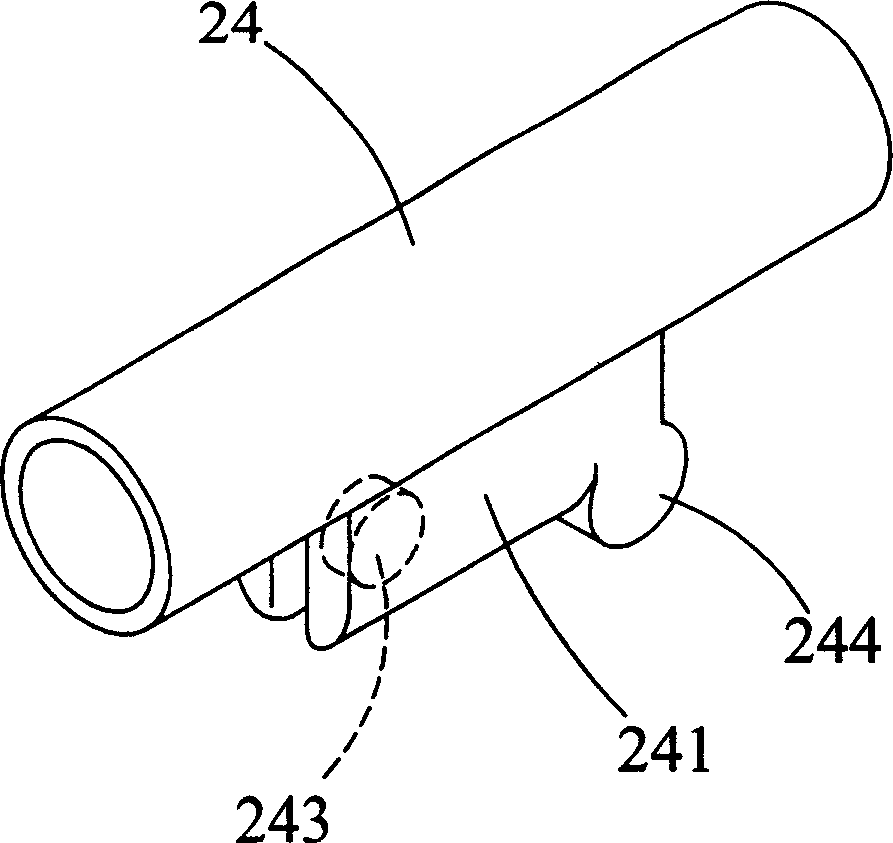
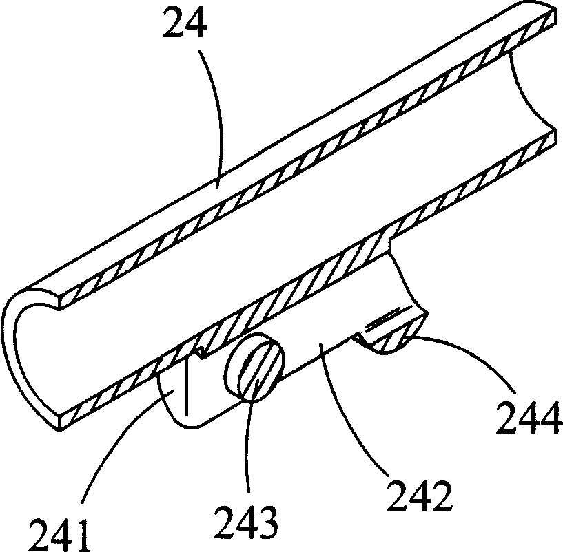
[0022] As shown in Figures 1 to 5, the umbrella rib positioning structure of the present invention includes a main shaft 10 and an umbrella rib mechanism 20, and a first nest 11 and a second nest 12 are pivotally arranged on the main shaft 10. The first nest body 11 and the second nest body 12 are respectively provided with a plurality of sockets 111, 121, and between the first nest body 11 and the second nest body 12 there is an extension spring 13 against it; the umbrella rib mechanism 20 is It includes a plurality of supporting ribs 21, a main rib 22 and a pull rod 23. The supporting ribs 21 are pivotally connected to the slot 121 of the second nest body 12, and a pivoting piece 24 and an end pivot are sleeved on it. Connecting member 25, wherein the bottom edge of the pivoting member 24 is provided with a lug 241, and the lug 241 has a perforation 242 and pivot pins 243 and stoppers 244 at both ends of the perforation 242 (such as image 3 shown); the main umbrella rib 22 ...


PUM


Abstract

A locating structure for the ribs of umbrella is composed of a mainshaft pivoted with the first and the second holders, and a rib mechanism consisting of the multiple supporting ribs pivoted to the second holder via their pivot elements with lug comprising pin and stop block and the multiple pull rods with one end pivoted to the first holder and another end pivoted to said pin. Its advantages are high strength and long service life.

Description

technical field [0001] The invention relates to an umbrella rib structure, in particular to an umbrella rib positioning structure which can make the supporting connection of the umbrella rib not easy to fall off, thereby ensuring the assembly and use quality of the umbrella rib. Background technique [0002] Umbrellas or parasols are commonly used items in modern people's lives. Whether they are sheltering from wind and rain or preventing sun exposure, they can bring considerable convenience. The failure rate of general umbrellas is quite high, and the main reason is that the joints between the ribs of umbrellas often cannot withstand various customary operations or relatively harsh use environments. As shown in Figure 7, 7A and Figure 8 As shown, the existing umbrella structure mainly includes a central axis rod 90 together with the handle, on which the central axis rod 90 is provided with a slidable first nest body 91, a second nest body 92 and an extension spring 93 abut...

Claims


Application Information

Patent Timeline
IPC IPC(8): A45B25/02A45B25/06
Inventor 游清泉
Owner 游清泉
Why Eureka
Try Eureka