
Frame lock with pivotable shackle and locking system for a bicycle

A technology of rotating locks and bicycles, which is applied to bicycle accessories, bicycle locks, and devices for preventing theft of bicycles. It can solve the problems of troublesome and expensive use of frame locks, and achieve the effect of simple operation

Inactive Publication Date: 2010-10-27
ABUS AUGUST BREMICKER SOEHNE AG
View PDF6 Cites 0 Cited by
  • Summary
  • Abstract
  • Description
  • Claims
  • Application Information

AI Technical Summary

Problems solved by technology

The structure of this interlocking device can be used for the interlocking of the rotating lock bar and the fixing of the safety rope at the same time, but it is not popular because of its high cost.
Furthermore, the use of such frame locks is cumbersome due to the need to operate the lever for rotating the locking lever on the one hand, the safety rope clamp on the other, and finally the original interlock

Method used


Image

  • Frame lock with pivotable shackle and locking system for a bicycle
  • Frame lock with pivotable shackle and locking system for a bicycle
  • Frame lock with pivotable shackle and locking system for a bicycle

Examples


Embodiment Construction

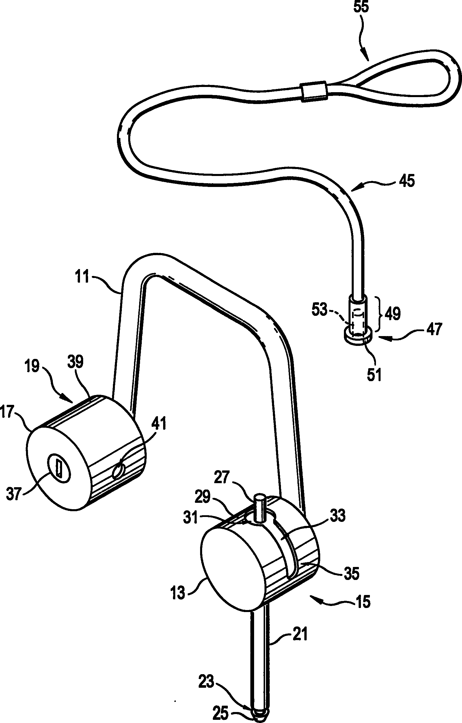
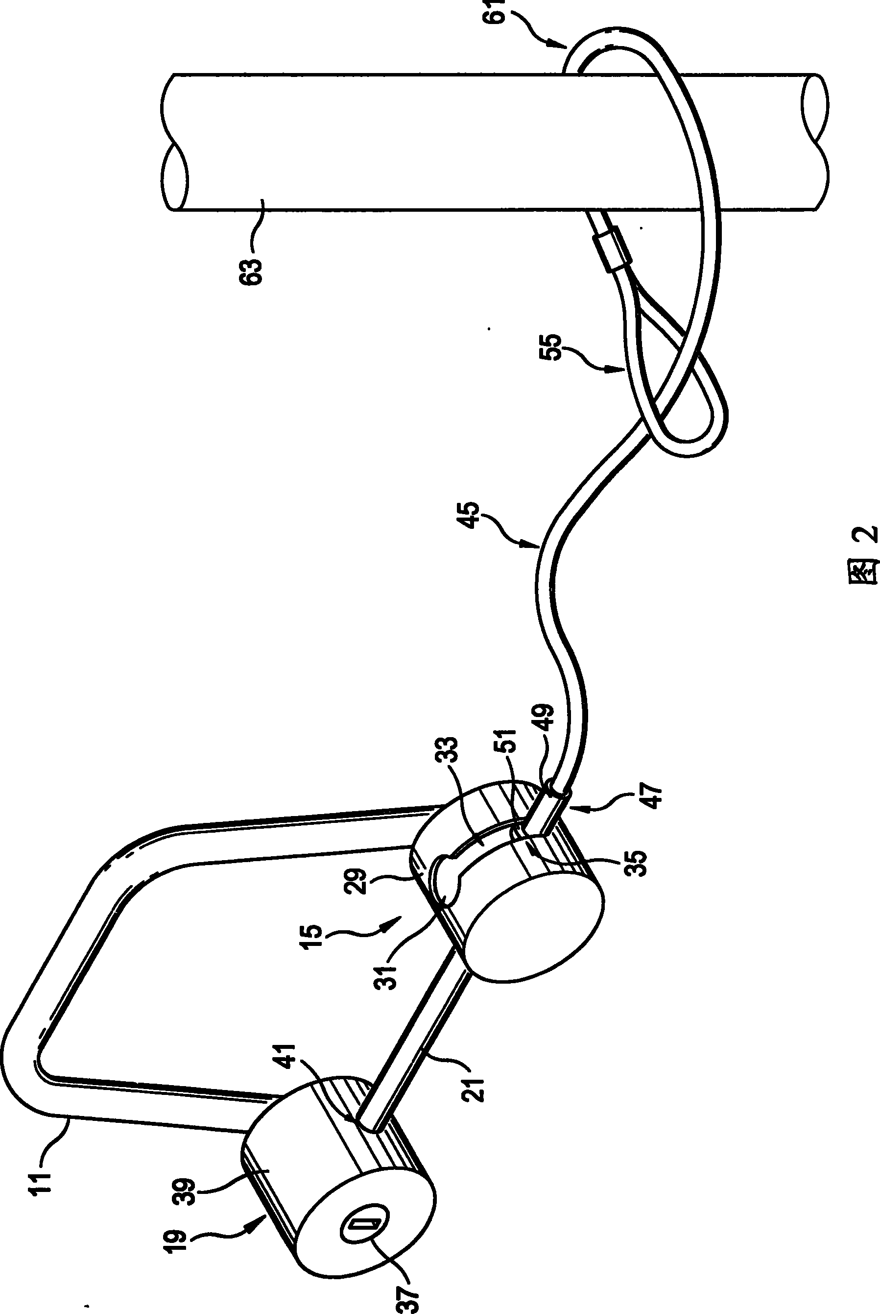
[0032] figure 1It is a rotating lock bar-frame lock in a perspective view, which has a substantially U-shaped connecting lock bar 11 . The cylindrical pot-shaped casing 13 of the lock bar support mechanism 15 is installed on one end of the lock bar 11, for example, by welding. The other end of the connecting lock bar 11 is equipped with a cylindrical pot housing 17 of a lock bar insertion mechanism 19 .

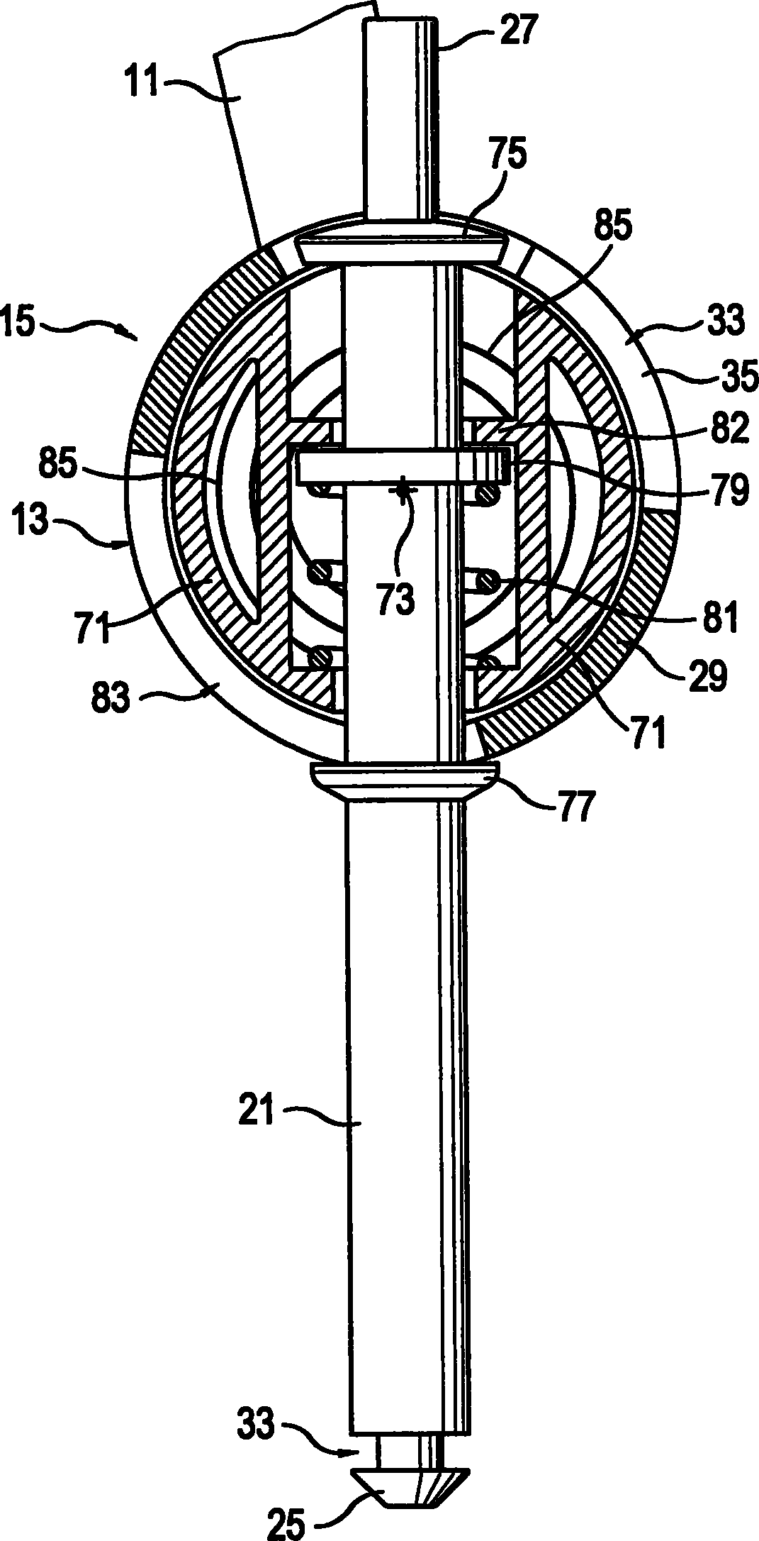
[0033] The straight rod-shaped rotary locking lever 21 is rotatably mounted on the locking lever supporting mechanism 15 . in accordance with figure 1 In the description of , the rotating lock lever 21 is in the vertical unlocking position. The free end of the rotating lock bar 21 has a lock bar head 25 with an inclined front end, and a convoluted interlocking groove 23 at its bottom end. The rotary locking lever 21 has a pin-shaped axial extension, that is, the operating lever 27 , at the other end relative to the locking lever support mechanism 15 . The joystick 27 pro...


PUM


Abstract

The invention relates to a rotary locking bar-framework lock. The lock has a locking bar supporting mechanism fixed with a rotary locking bar thereon, a locking bar inserting mechanism which is inserted by a free end of the rotary locking bar, operation bar for rotating the rotary locking bar and a fixing mechanism for fixing the safety rope on the framework lock. The fixing mechanism comprises arear end fastening portion. A rope clamp is able to be fixed thereon by means of the operation bar. The invention also relates to a safety system of a bicycle.

Description

technical field [0001] The invention relates to a rotary lock lever-frame lock for bicycles. Background technique [0002] The rotary lock bar-frame lock has a lock bar support mechanism and a lock bar insertion mechanism, and it is installed on the vehicle frame of the bicycle directly or by means of a fixed connecting lock bar. A rotary lock lever is rotatably mounted on the lock lever support mechanism, and it can rotate between an unlocked position such as a horizontal position and a locked position such as a vertical position, in which case the rotary lock lever on the locked position passes through the A wheel of a bicycle. In the locked position, the free end of the rotating locking lever is inserted into the locking lever insertion mechanism. The wheel can also be locked by turning the rotary locking lever into the locked position while being held in the locked position by means of the interlock. [0003] Furthermore, such rotary locking levers usually have an act...

Claims


Application Information

Patent Timeline
IPC IPC(8): E05B71/00B62H5/00B62H5/14
CPCB62H5/142E05B71/00B62H5/003
Inventor 托马斯·贝克
Owner ABUS AUGUST BREMICKER SOEHNE AG
Learn More