Air conditioner shell-and-tube condenser with built-in oil cooling device

An oil-cooled, shell-and-tube technology, used in evaporators/condensers, refrigerators, refrigeration components, etc., can solve the problems of inconvenient structural design and engineering installation of air-conditioning units, complicated layout of related pipelines, etc., and simplify equipment configuration. , The effect of reducing product cost and facilitating engineering installation

Inactive Publication Date: 2005-06-29
TELLHOW SCI TECH CO LTD
View PDF0 Cites 8 Cited by
  • Summary
  • Abstract
  • Description
  • Claims
  • Application Information

AI Technical Summary

Problems solved by technology

[0002] At present, the traditional air-conditioning condenser and oil cooler are arranged separately, which increases the equipment configuration of the entire air-conditio

Method used


Image

  • Air conditioner shell-and-tube condenser with built-in oil cooling device

Examples


Embodiment Construction

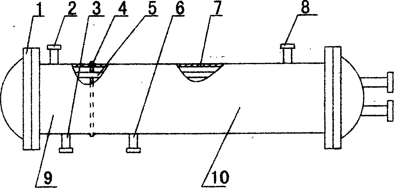
[0008] Such as figure 1 Shown, the present invention comprises oil cooling part (9) and condensing part (10), and oil cooling part and condensing part are connected in a cylinder (7), cut off with baffle plate (4) in the middle, the radiating pipe ( 5) Pass through the baffle and fix on the tube plates (1) at both ends, the compressor oil enters from the oil inlet pipe (2) and comes out from the oil outlet pipe (3), and the refrigerant enters from the refrigerant inlet pipe (8). Out of the refrigerant outlet pipe (6), the cooling water in the heat dissipation pipe cools the compressor oil while cooling the refrigerant, realizing the unification of the condenser and the oil cooler.


PUM


Abstract

A shell-and-tube condenser for air conditioning with its own oil cooling device, which includes an oil cooling part and a condensing part, the oil cooling part and the condensing part are connected in a cylinder, separated by a baffle in the middle, and the heat dissipation pipe in the cylinder passes through The baffles are fixed on the tube plates at both ends, and the cooling water in the cooling tube cools the compressor oil while cooling the refrigerant. The invention realizes the unification of the condenser and the oil cooler of the air-conditioning unit, simplifies equipment preparation, facilitates on-site engineering installation, and reduces product cost.

Description

technical field [0001] The invention relates to a shell-and-tube condenser for an air conditioner with a built-in oil cooling device Background technique [0002] At present, the traditional air-conditioning condenser and oil cooler are arranged separately, which increases the equipment configuration of the entire air-conditioning unit, and the related pipeline layout is more complicated, which brings inconvenience to the structural design and engineering installation of the air-conditioning unit. Contents of the invention [0003] The purpose of the present invention is to provide a shell-and-tube condenser for air-conditioning with its own oil cooling device, which brings convenience to the structural design and engineering installation of the air-conditioning unit. [0004] The present invention is achieved in this way, it includes an oil cooling part and a condensing part, the oil cooling part and the condensing part are ...

Claims


Application Information

Patent Timeline
IPC IPC(8): F25B39/04F28D3/02
Inventor 王建奎
Owner TELLHOW SCI TECH CO LTD
Why Eureka
Try Eureka