Rolling sliding vane pump

A technology of sliding vane pumps and sliding vanes, which is applied to pumps, pump components, rotary piston type/oscillating piston type pump components, etc., can solve problems such as poor performance, fast wear of sliding vanes and pump body, and improve reliability , solve heat, reduce friction effect

Inactive Publication Date: 2005-07-06
ZHEJIANG UNIV OF TECH
View PDF0 Cites 9 Cited by
  • Summary
  • Abstract
  • Description
  • Claims
  • Application Information

AI Technical Summary

Problems solved by technology

[0003] The present invention solves the disadvantages of fast wear and poor performance of the sliding vane and the pump body of the rolling vane pump with the above structure, and provides a rolling vane pump that greatly reduces the wear of the sliding vane and the pump body and changes sliding into rolling

Method used


Image

  • Rolling sliding vane pump
  • Rolling sliding vane pump
  • Rolling sliding vane pump

Examples


Embodiment Construction

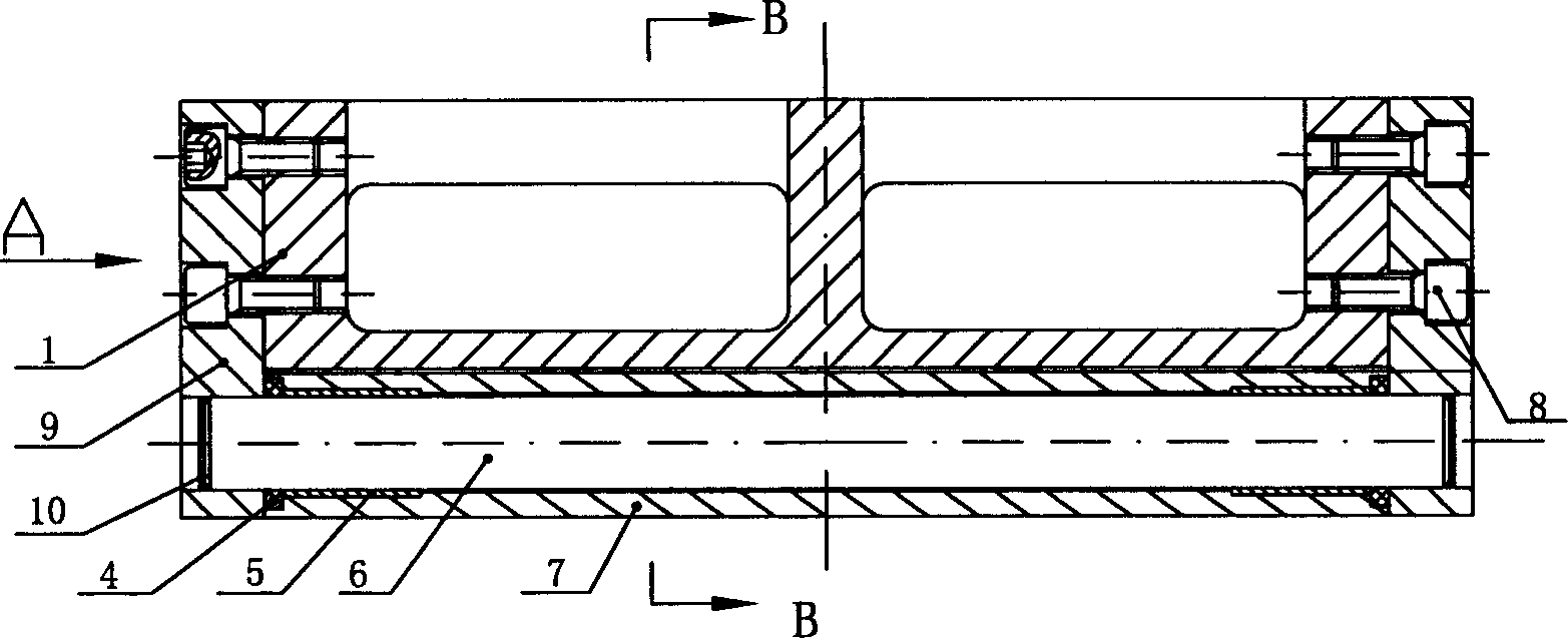
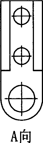
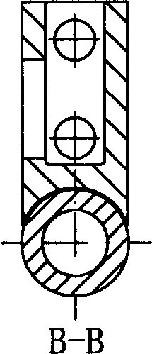
[0016] Referring to the accompanying drawings, a rolling vane pump includes a pump body 3, a rotor 2 with a groove in the axial direction, and a rolling vane 1 that can move radially in the groove, and the rolling vane includes a vane Body, roller seat and rolling device, the radially outer end of the slider body is fixed with an axial roller seat 9, and a rolling device is fixed on the roller seat, and the rolling device is fixed on the roller through the shaft 6 On the column seat, there is a gap between the rolling device and the slide body. The rolling device includes: a shaft 6, a bearing 5, and a roller 7 fixed in the axial hole of the roller seat. The bearing 5 is fixed in the roller 7 , and the bearing 5 is supported by the shaft 6 . The axially outer ends of the inner bearings 5 ​​of the roller seat 9 are respectively provided with bearing retaining rings 4, and the axial holes of the roller seat 9 are provided with shaft retaining rings 10, and the roller seat and th...


PUM


Abstract

This invention relates to rolling slide pump, which comprises pump, rotator along axis with flute and the rolling slide moving radial. The said rolling slide comprises slide body, rolling column socket and rolling device. The said slide both ends are fixed with axis rolling column socket. The said rolling column socket is fixed with rolling device which is fixed on the rolling column socket through axis. The said rolling device is at an interval with the said slide. The said rolling device comprises axis, axletree and rolling column fixed on the rolling column socket.

Description

(1) Technical field [0001] The invention relates to a brand new rolling vane pump. (2) Background technology [0002] Sliding vane pump is a widely used volumetric rotor pump, mainly including pump body 3, vane 1 and rotor 2, such as Figure 4 . When the rotor rotates under the drive of power, the sliding vane is affected by centrifugal force and differential pressure, and the side of the sliding vane reciprocates in the groove of the rotor. At the same time, the outer circle of the rotor separates the pump inlet and outlet from the upper surface of the pump body, and slides at high speed. , the chamber formed by the sliding vane, the rotor and the pump body, when connected with the pump inlet, the volume of the chamber gradually increases, and the medium is sucked in; when it is connected with the pump outlet, the volume of the chamber gradually decreases, and the medium is discharged. Due to the relative sliding between the sliding vane and the inner surface of the pump b...

Claims


Application Information

Patent Timeline
Patent Type & Authority Applications(China)
IPC IPC(8): F04C2/356F04C29/00
Inventor 张生昌陈晗峰鲍雨梅徐松樟
Owner ZHEJIANG UNIV OF TECH
Why Eureka
Try Eureka