Humidifying device and air conditioner

A humidification device and humid air technology, applied in air conditioning systems, air humidification systems, heating methods, etc., can solve the problems of increasing costs and increasing the size of humidification devices, and achieve the effect of miniaturization and reduction

Inactive Publication Date: 2005-07-13
SAMSUNG ELECTRONICS CO LTD
View PDF2 Cites 0 Cited by
  • Summary
  • Abstract
  • Description
  • Claims
  • Application Information

AI Technical Summary

Problems solved by technology

[0006] However, in the above-mentioned conventional humidifiers, since each vaporization net needs a blower and a heater, when using multiple vaporization nets to increase the humidification capacity, a plurality of blowers and heaters are required. The heating machine increases the overall size of the humidifier, and there is a problem of increasing the considerable cost.

Method used


Image

  • Humidifying device and air conditioner
  • Humidifying device and air conditioner
  • Humidifying device and air conditioner

Examples


no. 1 Embodiment

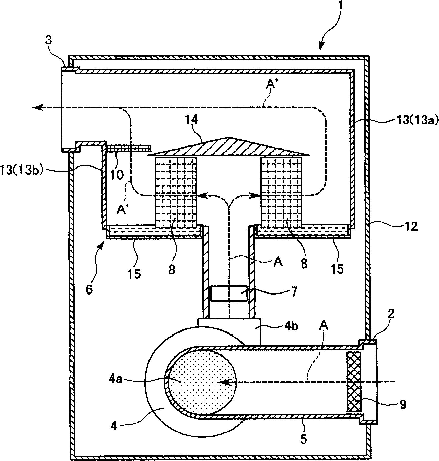
[0033] First, the humidifier 1 that sucks in indoor dry air A and discharges humid air A' will be described. Such as figure 1 As shown, the humidifier 1 is composed of a suction port 2 that inhales dry air A, an exhaust port 3 that discharges humid air A', a blower 4 that delivers air from the suction port 2 to the discharge port 3, and is installed between the suction port 2 and the blower. 4 between the suction air duct 5, the exhaust air duct 6 installed between the blower 4 and the air outlet 3, the heater 7 that heats the dry air A sent from the blower 4, and the dry air A passes through to form the wet air A The vaporization net 8 in the wet state of ', the air cleaning body 9 for cleaning the dried air A sucked in from the suction port 2, and the first air damping body 10 for passing the moist air A' and reducing the air volume .

[0034] The suction port 2 and the air discharge port 3 are respectively fitted on the housing 12 of the humidifier 1 which accommodates th...

no. 2 Embodiment

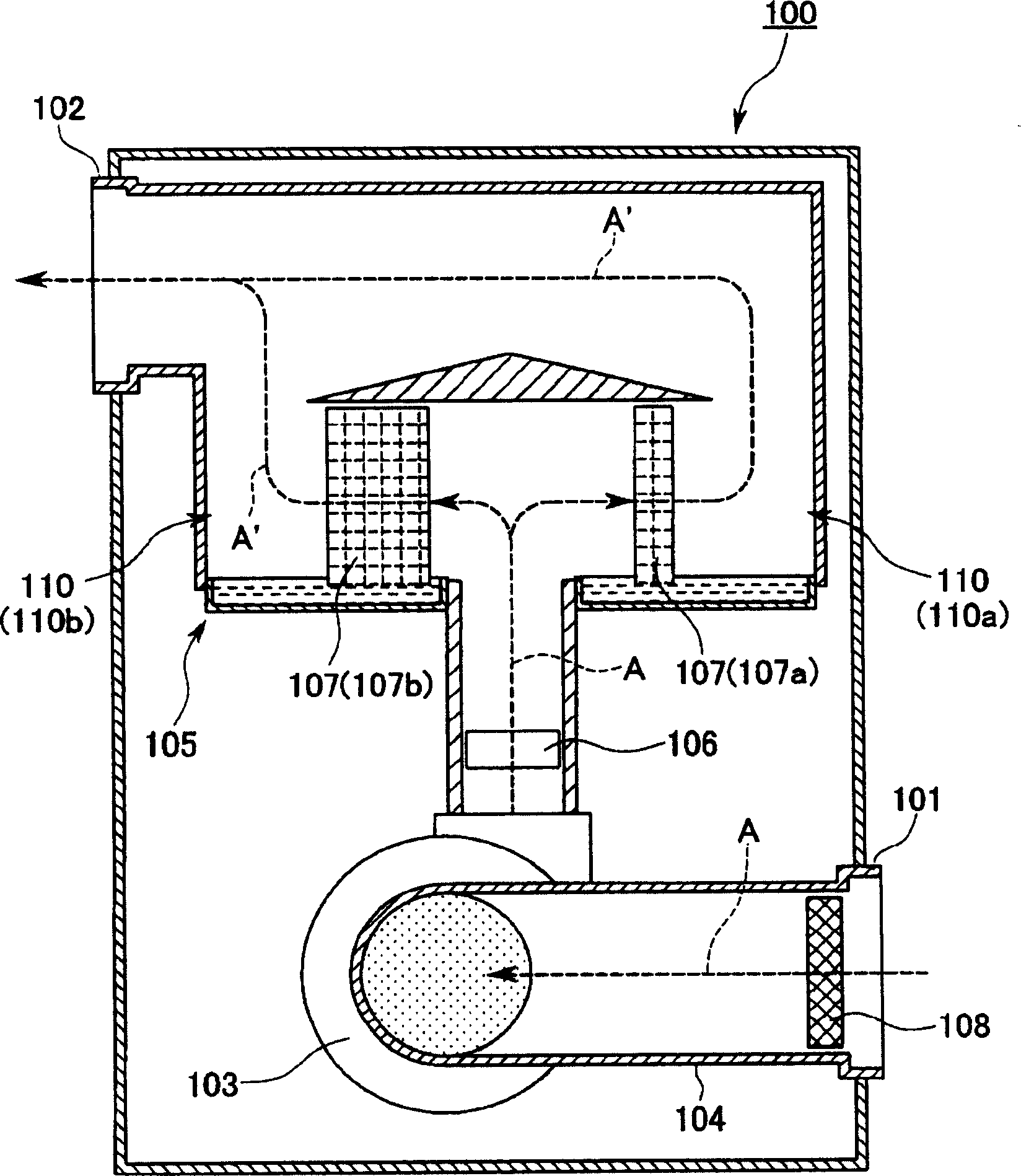
[0050] Such as image 3 As shown, the humidifier 100 is composed of a suction port 101 , an air exhaust port 102 , a blower 103 , a suction air duct 104 , an exhaust air duct 105 , a heater 106 , a vaporization net 107 , and an air cleaning body 108 . In the middle part of the exhaust air duct 105, two branch air ducts 110 that are divided into two forks in front of the heater 106 and merged in front of the air outlet 102 are formed. 110b is long, and inside the two branch air ducts 110a, 110b, vaporization nets 107 are installed respectively. The vaporization net 107a used in one (longer) branch air duct 110a is thinner than the other vaporization net 107b interposed in the other (shorter one) branch air duct 110b, and The air permeability is large.

[0051] According to the above-mentioned humidifying device 100, among the two vaporizing nets 107, the vaporizing net 107a sandwiched in the branch air duct 110a of one side (the longer side) is sandwiched with the other side ...

no. 3 Embodiment

[0053] Such as Figure 4 As shown, the humidifier 200 is composed of a suction port 201 , an air exhaust port 202 , a blower 203 , a suction air duct 204 , an exhaust air duct 205 , a heater 206 , a vaporization net 207 , and an air cleaning body 208 . In the middle of the exhaust air duct 205 , two branch air ducts 210 that are divided into two forks in front of the heater 206 and converge in front of the air exhaust port 202 are formed. The branch air duct 210 is divided into upper and lower regions from the center of the middle portion of the exhaust air duct 205 formed in a chamber shape by a partition member 211, and the two branch air ducts 210a and 210b are formed in the same shape. Specifically, one end of the exhaust air duct 205 directly connected to the air outlet 203a of the blower 203 is formed below the center of the partition member 211, and the other end of the exhaust air duct 205 directly connected to the air outlet 202 portion is formed above the center of ...


PUM


Abstract

A humidification device and an air conditioner, the humidification device (1) has: a suction port (2) for inhaling dry air (A), an air discharge port (3) for discharging humid air (A'), and an exhaust port from the suction port The air blower (4) for conveying air through the mouth, the suction air duct (5) installed between the suction inlet and the air supply fan, the exhaust air duct (6) installed between the air supply fan and the air exhaust outlet, and the exhaust air duct And heat the heater (7) of the dry air sent from the blower, the vaporization net (8) that is clamped in the exhaust air duct in front of the heater and becomes wet air and wet state when the dry air passes through; The middle part of the duct (6) forms a plurality of branch air ducts (13) that are divided into two forks in front of the heater (7) and converge before the air outlet (3). Equipped with vaporization net (8). The humidifying device and the air conditioner can greatly increase the humidifying capacity, and can achieve miniaturization and cost reduction.

Description

technical field [0001] The present invention relates to a humidifying device which sucks dry air and discharges humid air, and an air conditioner provided with the humidifying device. Background technique [0002] A humidifier is generally a device that uses a heater to heat the dry air sent to the air passage by a blower and passes the heated air through a humidified vaporization network to generate humid air. When the heated air passes through the evaporating net, the heat of the heated air is used to vaporize the moisture soaked in the evaporating net into steam, and the steam is mixed with the dry air to generate humid air. The vaporization net is immersed in the water stored in the water pan (water tank), and the vaporization net absorbs the water in the water pan by capillary phenomenon and is wetted (for example, refer to Patent Document 1). [0003] Enlarging the area of ​​the vaporization net can increase the humidification capacity of the humidifier, but the heigh...

Claims


Application Information

Patent Timeline
IPC IPC(8): F24F6/04F24F3/00F24F3/147F24F6/00
CPCF24F6/04F24F13/10F24F2006/008F24F6/025F24F8/117F24F13/20F24F8/80F24F2013/205F24F2221/34
Inventor 胁坂英司多久岛朗
Owner SAMSUNG ELECTRONICS CO LTD
Why Eureka
Try Eureka